Common ground.Reference point for both traces? DGND? AGND? Common Ground?
"Zener stacked shunt with pass PNP"Power supply Arrangements?
44.1kSignal/sample rate supplied to TDA1541?
I couldn't really hear a difference either, but I figured presenting a lower impedance should be beneficialPast that, below 20kHz I see no systemic difference (100 sample window at high bandwidth).
in some way.
22u panasonic os-con.Decoupling (what value capacitor)
Yes, this was measured with music playing with 25mV output compliance met. I think I might have been using EUVL's CEN current conveyer at the time. Which I believe presented about a 12R load,If so, we are back at the series connected 20V shunt regulator chain (5V+5V+10V) I have been using for several builds as the best option. In this case all currents reliably circularise, as long as a low impedance return path for Iout L+R is offered.
Thank you for clarification.
If we go with my original TL431 & PNP chain plus 1,200uF (or 1,000uF) Os-Con in parallel with each shunt , we get the result.
I think after looking at all the discussions, tests etc this seems best. We need to add ballast resistors to even out currents.

Like this we get in effect 60mA from +5V to -15V with a few mA error current flowing into the shunts. This suggests ~ 80...100mA current into the whole system. So we end up with (say) this again:

This PSU will be ~ 36mOhm or less between +5V and -15V from below 300kHz pretty much to DC with a minimum ~ 6mOhm (quick back of envelope calc).
The included PSUD screen shows how effective the RC chain is in killing noise. I doubt any more effort will give material improvements, objective or subjective. For that it's quite minimal really.
If dividing PSU and DAC onto separate PCB's, the shunts etc. should be on the same PCB as the DAC.
My only other comment is, that a dual-mono DAC with one TDA1541 per channel looks more and more attractive.
Thor
If we go with my original TL431 & PNP chain plus 1,200uF (or 1,000uF) Os-Con in parallel with each shunt , we get the result.
I think after looking at all the discussions, tests etc this seems best. We need to add ballast resistors to even out currents.
Like this we get in effect 60mA from +5V to -15V with a few mA error current flowing into the shunts. This suggests ~ 80...100mA current into the whole system. So we end up with (say) this again:
This PSU will be ~ 36mOhm or less between +5V and -15V from below 300kHz pretty much to DC with a minimum ~ 6mOhm (quick back of envelope calc).
The included PSUD screen shows how effective the RC chain is in killing noise. I doubt any more effort will give material improvements, objective or subjective. For that it's quite minimal really.
If dividing PSU and DAC onto separate PCB's, the shunts etc. should be on the same PCB as the DAC.
My only other comment is, that a dual-mono DAC with one TDA1541 per channel looks more and more attractive.
Thor

Have some new unused oieces S1 and S2 too. From original philips spare parts from discounted CD players in local radio station...But it harder to have two S1 or two taiwann 1998 TDA1541A !
They ordered mostly S2, each in own box for eventual spare parts, But obviously they didnt have malfunctions almost at all.
That was before 25-30 years ago. 🙁
.
It was also huge stock in the local electro material stores. I remeber once was buy maybe 11 pieces left in the stock for years. Nobody wants them in tese time. Was to much expectations from new dac chip models i suppose?
.
That is what I meant with "try to make equal distribution of power" with shunt end.I think after looking at all the discussions, tests etc this seems best. We need to add ballast resistors to even out currents.
Prior DAC power pins and decoupling.
Version 9.3.150.328 SF-TI
Thor
TDA1541 meet David Copperfield
Ok, I mentioned "Balanced TDA1541" a few times, let me explain in detail what this gets us (and what not).
Now what does David Copperfield have to do with all of this? Well, those of a certain age will remember David Copperfield with great envy. Not only did he get to do all sorts of naughty things to Claudia Schiffer, but he could make huge things disappear. Of course, it were illusions, but still, impressive guy!
So what do we want to disappear in the context of the TDA1541?
Our discussions have focused on the various noise / disturbance etc. sources on various pin's.
Our aim is to make as much of these disturbance's disappear, so they do not cause problems elsewhere.
So we are trying to be like David Copperfield and make stuff disappear.
If we operate the TDA1541 "balanced" as single chip per channel we do a major disappearing act.
Let's see what disappears, shall we?
Definitely a vanishing act worth it from a viewpoint of design clarity and isolation.
So is it worth doubling up the TDA1541?
If you can get enough of them, which I can (I'm now up to 5 X Sony CDP-750/950 at low cost) definitely. With a modern PCB with SMD Capacitors for much of the IC decoupling it's not that hard to do.
The I/U conversion, if discrete, get's more complex, but we have a benefit here too. The Base Current of the input transistors will be appx. complementary (especially if matching transistors for beta) and thus also cancel to zero.
So now I need to think more on the balanced setup and the I/U conversion.
Thor
Ok, I mentioned "Balanced TDA1541" a few times, let me explain in detail what this gets us (and what not).
Now what does David Copperfield have to do with all of this? Well, those of a certain age will remember David Copperfield with great envy. Not only did he get to do all sorts of naughty things to Claudia Schiffer, but he could make huge things disappear. Of course, it were illusions, but still, impressive guy!
His illusions have included the disappearance of a Learjet aircraft (1981), the vanishing and reappearance of the Statue of Liberty (1983), levitating over the Grand Canyon (1984), walking through the Great Wall of China (1986), escaping from Alcatraz prison (1987), the disappearance of an Orient Express train dining car (1991) and flying on stage for several minutes (1992).
So what do we want to disappear in the context of the TDA1541?
Our discussions have focused on the various noise / disturbance etc. sources on various pin's.
Our aim is to make as much of these disturbance's disappear, so they do not cause problems elsewhere.
So we are trying to be like David Copperfield and make stuff disappear.
If we operate the TDA1541 "balanced" as single chip per channel we do a major disappearing act.
Let's see what disappears, shall we?
- Audio current in Pin 28 (+5V) - this gets nulled to +/- 1/2 LSB mostly semi-random stuff around Fs. This is a biggie.
- Data related current in the input PNP's cancels out. Not as big, but each of the 4 inputs draws some signal dependent current (see most likely schematic in this post) There definitly are a few mA involved, balanced operation makes this set of currents cancel for Data, so the only disturbance's on+/-5V are clock related and unless we use the "stopped clock" operation, they are continuous and steady thus not an issue in terms of PSU modulation which can cause .
- Any mechanisms inside the TDA1541 that cause data related leakage into supplies or audio is cancelled also.
- If we use re-clockers with 74F74 (some of the lowest jitter other than ECL and hard to use exotic CMOS) and load outputs equally, again, signal dependent currents do a disappearing act.
Definitely a vanishing act worth it from a viewpoint of design clarity and isolation.
So is it worth doubling up the TDA1541?
If you can get enough of them, which I can (I'm now up to 5 X Sony CDP-750/950 at low cost) definitely. With a modern PCB with SMD Capacitors for much of the IC decoupling it's not that hard to do.
The I/U conversion, if discrete, get's more complex, but we have a benefit here too. The Base Current of the input transistors will be appx. complementary (especially if matching transistors for beta) and thus also cancel to zero.
So now I need to think more on the balanced setup and the I/U conversion.
Thor
And it sounds awesome, especially when using a 22u PML (Rubycon) as bypass cap to lower zout to 3 mohms (simulated). Not sure how close in reality I got.I think after looking at all the discussions, tests etc this seems best.
When I ran balanced in one DAC (one channel inverted) the current demand being much closer to constant, I could take out the bypass cap (giving higher zout) and the sound was almost the same, but when running single ended without the bypass cap, the dynamic powerful bass was diminished. In the circuit you posted ref C1, C7, C2 100u, would you recommend os-con here too?My only other comment is, that a dual-mono DAC with one TDA1541 per channel looks more and more attractive.
Having said all that - I am very curious how your super cap variation of the circuit would sound.
Another idea from you that caught my attention was when you were speaking about line regulation/power conditioning, slightly off topic but id be interested to hear what you are using, and also you mentioned something about an AC motor coupled to an AC generator as a power source.
Cheers Thor
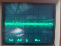
I measured this with music playing by using the "poor mans differential probes" technique with 50R terminators.
I had one probe on each AOL, AOR output (normal and inverted) and then used the add and invert functions which left me with this wave form (actual V level much lower due the measuring technique flaw), which I suppose is the common mode noise that will be canceled out when converting back to SE.
Load was around 15RIV. To me the overall sound was excellent when using a DAC this way, Might couple well with a SE tube circuit to add some H2 back.
Attachments
Edit: no invert functionand then used the add and invert functions
When I ran balanced in one DAC (one channel inverted) the current demand being much closer to constant, I could take out the bypass cap (giving higher zout) and the sound was almost the same, but when running single ended without the bypass cap, the dynamic powerful bass was diminished.
Interesting. Also makes sense.
In the circuit you posted ref C1, C7, C2 100u, would you recommend os-con here too?
No, they only set the shunt's to an AC gain of unity, so they are more like audio coupling capacitors. I doubt Nichicon Muse (U)ES are needed, so any decent quality electrolytic cap will do.
Having said all that - I am very curious how your super cap variation of the circuit would sound.
Me too, it will come.
Another idea from you that caught my attention was when you were speaking about line regulation/power conditioning, slightly off topic but id be interested to hear what you are using, and also you mentioned something about an AC motor coupled to an AC generator as a power source.
I am poor and only use straight wall current, with a humungous EI 230V : 100V stepdown as a lot of my gear is Japan standard (100VAC).
The Asynchronous AC motor with governor (could also be DC) and synchronous AC generator is an old large scale (easily 100's of kW) voltage and frequency stabiliser for example for industrial plants, back when plant's had massive varying interesting loads and also needed a stable supply for controls.
In 2024 I guess a Sinewave invertor would be the modern choice.
Thor
How balanced is your balanced dac?
When I was playing with this stuff, I tried TDA1543A with one chip per channel, differential data (L+/L- on chip 1, R+/R- on chip 2).
Then I asked myself, how well are the channels matched inside each chip? I reprogrammed the CPLD to send the same data to the channels (without inversion), and then I listened to the "residue" with the dacs connected directly to my power amp (inherently balanced/differential based on THS4131). Only 1 of a handful of TDA1543A had acceptable channel matching, meaning the residue was very low in volume. I didn't bother looking at the waveform, I just listened.
It has been told many times in this thread about the unmatched L and R output of the TDA1541A , especialy if the chips are not from the same batch
.
.
How balanced is your balanced dac?
When I was playing with this stuff, I tried TDA1543A with one chip per channel, differential data (L+/L- on chip 1, R+/R- on chip 2).
1543 is problematic. It misses the whole set of current systems from the earlier, high performance chip's.
TDA1541A lists < 0.1dB typical and 0.3dB worst case.
For 0.1dB, the 4mA audio current leaves 46uA difference at full scale and 0.3dB leaves 140uA difference at full scale.
Good enough I think. With 0.1dB we get ~ -40dB CMRR for audio.
Thor
TDA1541A lists < 0.1dB typical and 0.3dB worst case.
For 0.1dB, the 4mA audio current leaves 46uA difference at full scale and 0.3dB leaves 140uA difference at full scale.
Good enough I think. With 0.1dB we get ~ -40dB CMRR for audio.
Datasheet says from 3,4 to 4,6 mA , and in the real life it happens to be so , I have made measurements that goes that way too , adding the two output leads to great distortion , it has been seen here in this thread by Koldby , me and maybe some others
.
I measured it with 440 Hz full scale, using a 3 1/2 digit DMM.
L: 1.506 mA rms
R: 1.485 mA rms
That is 2.13 / 2.10 mA peak, 4.26 / 4.20 mApp. This is on an R1 grade.
Trying to measure the residual distortion of L-R, what do you recommend? A center tapped trafo would be good.
L: 1.506 mA rms
R: 1.485 mA rms
That is 2.13 / 2.10 mA peak, 4.26 / 4.20 mApp. This is on an R1 grade.
Trying to measure the residual distortion of L-R, what do you recommend? A center tapped trafo would be good.
Taken separately the outputs seems quite similar indeed , adding them leads to high level of distortion as it has been seen before in the thread , but I have to say that it was on passive setup , Koldby had found an solution to adjust the output leading to low distortion figures , I did myself the same job with the same results
.
.
- Home
- Source & Line
- Digital Line Level
- Building the ultimate NOS DAC using TDA1541A