I discussed the internal loudspeaker enclosure (peak) pressure in another thread.
When trying to find possible simulation of that pressure in hornresp I found the internal port pressure for ported speakers - can this be taken as the "general" internal enclosure pressure?
And is there a way to calculate or plot the internal enclosure pressure of a sealed speaker?
When trying to find possible simulation of that pressure in hornresp I found the internal port pressure for ported speakers - can this be taken as the "general" internal enclosure pressure?
And is there a way to calculate or plot the internal enclosure pressure of a sealed speaker?
not entirely clear on MEH model tap locations.
As far as the simulation model is concerned it doesn't matter if the horn cross-section is circular or rectangular. If it is rectangular then it doesn't matter if the tap is located in a corner or in the middle of a side.
The length along the horn wall is not a factor in the model. What is important is the axial distance from the plane of the tap position back to the horn throat, as shown by the red line in the image below. For the given example the axial length equals L12 + L23 = 55 cm.
I found the internal port pressure for ported speakers - can this be taken as the "general" internal enclosure pressure?
If the resonances masked option is selected then the pressure on the rear side of the diaphragm will be the same as the port inlet pressure. If the resonances not masked option is selected, then there will be a slight difference in pressure.
* To find the pressure on the rear side of the diaphragm, display the Diaphragm Displacement chart and then select the menu commands Tools > Diaphragm Pressure > Rear Chamber Side.
is there a way to calculate or plot the internal enclosure pressure of a sealed speaker?
As for the ported speaker above *.
Simple sanity check for 10 litre sealed chamber loudspeaker.
From Boyle's law:
P1 * V1 = P2 * V2
Given:
P1 = 101.325 kPa (standardised atmospheric pressure at sea level)
V1 = 10 litres (volume of sealed enclosure)
Sd = 350 cm2
Xmax = 5 mm
Then:
V3 = (350 * 5 / 10) / 1000 = 0.175 litres
V2 = V1 - V3 = 10 - 0.175 = 9.825 litres
Differential pressure P2 at Xmax:
P2 rms (DC) = P1 * (V1 / V2 - 1)
P2 peak = Sqrt(2) * 101.325 * 1000 * (10 / 9.825 - 1) = 2552 Pa
Hornresp calculates the peak pressure value to be 2495 Pa.
The simplified calculation gives a result that is surprisingly close to the more accurate Hornresp value, the difference being a mere 2 percent.
That's amazing!* To find the pressure on the rear side of the diaphragm, display the Diaphragm Displacement chart and then select the menu commands Tools > Diaphragm Pressure > Rear Chamber Side.
There are even more features in hornresp, you just have to look for them ...
Thank you very much for pointing me to it and thanks even more for the calculation method!
So you think, that hornresp simulation is not correct in my case? I can get rid of 160 hz resonance in simulation as can be seen on my screenshot (by adjusting second segment's length). I just don't know how to account for the bend correctly.The project you are planning is very much just a bass reflex design with a long port. The port length resonance around 160 Hz for 110 cm length (half wavelength for open tube) will be amplified by the quater wave reflection at half port length bend and cannot easily be attenuated, unless you install some kind of resonator/absorber.
Just try it out in hornresp.
Another possible solution could be a MLTL with driver and port offset from the line ends. You probably need a smaller port in this case.
Just wanted to say thank you David. The program is really a work of Genius. Just built a pair of speakers and hornresp was extremely accurate thank you again
Sorry, I thougt that was another TL layout! Seems to be ok then!I can get rid of 160 hz resonance in simulation as can be seen on my screenshot
but in real horns there IS a difference between a tap being in the corner or middle of a side. People say this is due to the pressure being lower in the corners. But isn't the pressure lower because - due to the curved wavefront - the corner taps are further from the throat, despite having the same axial distance as a tap in the centre of a side.As far as the simulation model is concerned it doesn't matter if the horn cross-section is circular or rectangular. If it is rectangular then it doesn't matter if the tap is located in a corner or in the middle of a side.
The length along the horn wall is not a factor in the model. What is important is the axial distance from the plane of the tap position back to the horn throat, as shown by the red line in the image below. For the given example the axial length equals L12 + L23 = 55 cm.
View attachment 1364484
But isn't the pressure lower because - due to the curved wavefront - the corner taps are further from the throat
The Hornresp MEH model assumes an axisymmetric horn and plane wavefronts. If you wish to simulate your design more precisely than that, then you will need to use a different program.
Simple sanity check for 10 litre sealed chamber loudspeaker.
From Boyle's law:
P1 * V1 = P2 * V2
Given:
P1 = 101.325 kPa (standardised atmospheric pressure at sea level)
V1 = 10 litres (volume of sealed enclosure)
Sd = 350 cm2
Xmax = 5 mm
Then:
V3 = (350 * 5 / 10) / 1000 = 0.175 litres
V2 = V1 - V3 = 10 - 0.175 = 9.825 litres
Differential pressure P2 at Xmax:
P2 rms (DC) = P1 * (V1 / V2 - 1)
P2 peak = Sqrt(2) * 101.325 * 1000 * (10 / 9.825 - 1) = 2552 Pa
Hornresp calculates the peak pressure value to be 2495 Pa.
The simplified calculation gives a result that is surprisingly close to the more accurate Hornresp value, the difference being a mere 2 percent.
View attachment 1364494
Hello there is not a lick of sanity here.
Boyle's law assumes that temperature stays constant. What you are discussing is is adiabatic compression.
Where did Xmax come from? Who speaks of Xmax in a sealed enclosure?
We should be discussing a constant voltage sine sweep where X excursion gets what it gets.
For a given driver in a given sealed enclosure the force on the diagram is the sum of the pressure inside the sealed enclosure * Sd + the force generated by the driver motor. That summed force can easily equal zero. (to keep it simple I left out things like compliance).
I visualize a transfer function where X excursion flattens out with decreasing frequency.
Thanks DT
Hello there is not a lick of sanity here.
Unfortunately it would seem that you have completely missed the point of the exercise.
"A sanity check or sanity test is a basic test to quickly evaluate whether a claim or the result of a calculation can possibly be true."
https://en.wikipedia.org/wiki/Sanity_check
Okay it can not possibly be true!Unfortunately it would seem that you have completely missed the point of the exercise.
"A sanity check or sanity test is a basic test to quickly evaluate whether a claim or the result of a calculation can possibly be true."
Just to clarify, Hornresp analyses the complete lumped-element electro-mechano-acoustical equivalent circuit of a loudspeaker. It does not use the sanity check method I described, if that is what you are thinking.
Hi,
i played around with a front loaded horn, and modeled the horn in a way that it is a plane with a small hole in front of the cone.
This extended HF way up to 8Khz and FR is flat. I wonder if this can work in reality, or if this cannot be build the way it was simulated.
Can someone give me a pointer why this might fail to work, because it feels to me that this cannot work out.
Thanks! Hornresp record is attached.


For comparison here is the same woofer as closed box:

i played around with a front loaded horn, and modeled the horn in a way that it is a plane with a small hole in front of the cone.
This extended HF way up to 8Khz and FR is flat. I wonder if this can work in reality, or if this cannot be build the way it was simulated.
Can someone give me a pointer why this might fail to work, because it feels to me that this cannot work out.
Thanks! Hornresp record is attached.
For comparison here is the same woofer as closed box:
Attachments
just as a coincidence I am dealing with a very similar project!Can someone give me a pointer
some issues I can see:
- the rear chamber bass-reflex vent is extremely small (only 1,2 cm2 port surface). this will cause turbulence and compression, but it's easily solvable by increasing port lenght and suface.
- the very thin front "horn" length will be difficult to produce - it will be thicker than a sharp edge of a 0,1 cm long horn
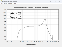
- there will be a volume in front of the driver that will act as a bandpass in combination with the 2 cm2 opening (use Vtc and Atc to define it). this may also cause a peak at the upper bandpass limit. also keep in mind the cone needs some space to move.
- the different propagation lengths between center and perimeter of the diaphragm will cause some cancellations. but that will not be a big issue, because the bandwidth is limited anyway.
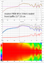
also keep in mind that FRS8-M has a rising response.
this is the response of this driver in a 3 liter sealed enclosure.
the rise above 800 Hz up to about 3 kHz is the baffle step. above 3 kHz the driver is starting to beam and the baffle has low influence.
you defined a 2pi-radiation that would neutralise the baffle step in my measurement. but this would require installation in the wall (ceiling/floor/very big baffle).

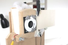
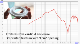
I made some tests with a resistive cardioid enclosure using FRS8 (with the small magnet and high Qts). the reduction "disc" in front of the cone is a 3d-printed frustum to reduce the driver front chamber. the opening is 34 mm in diameter (roughly 9 cm2).

here is the respective response - disregard the falling slope below 1 kHz, that is the resistive cardioid enclosure.
the rise from 1 kHz to 2,2 kHz is the "bandpass peak". above 2.2 kHz is the falling bandpass slope, with some further peaks above 10 kHz ("port resonances" or direct radiation through the hole).

here is your hornresp simulation but with an added volume in front of the cone:

let me know if you need further information!
Last edited:
That's good to hear.Sorry, I thougt that was another TL layout! Seems to be ok then!
But how to properly account for the bend?
I tried to search for the answer, but I feel, that if I use the centerline method (usually suggested), it would not give good results in this case, as speaker is directly in the bend and first segment is much bigger, than second.
From speaker's perspective the segment's lenght might even be the internal depth (which would mean omitting the bend's lenght totally).
Either some more advanced simulation (abec, akabak ...) or you just build it, maybe just a rough test enclosure.But how to properly account for the bend?
It matters a lot less than you are worrying about. Take a center path measurement around the bend. If you are looking for a trap effect for the midrange being sent down into the Transmission line consider making a coupled cavity immediately behind the driver with some fibrous tangle to absorb it. Rockwool is a superb broadband absorber and I specify it in many designs. Works wonderfully.That's good to hear.
But how to properly account for the bend?
I tried to search for the answer, but I feel, that if I use the centerline method (usually suggested), it would not give good results in this case, as speaker is directly in the bend and first segment is much bigger, than second.
From speaker's perspective the segment's lenght might even be the internal depth (which would mean omitting the bend's lenght totally).
1. That also could have been solved by just use a closed rear chamber
- the rear chamber bass-reflex vent is extremely small (only 1,2 cm2 port surface). this will cause turbulence and compression, but it's easily solvable by increasing port lenght and suface.
- the very thin front "horn" length will be difficult to produce - it will be thicker than a sharp edge of a 0,1 cm long horn
- there will be a volume in front of the driver that will act as a bandpass in combination with the 2 cm2 opening (use Vtc and Atc to define it). this may also cause a peak at the upper bandpass limit. also keep in mind the cone needs some space to move.
- the different propagation lengths between center and perimeter of the diaphragm will cause some cancellations. but that will not be a big issue, because the bandwidth is limited anyway.
2. I thought about a thin stiff cardboard
3. Thanks for this info. This showed it won't work
4. I stopped thinking about because it won't work
also keep in mind that FRS8-M has a rising response.
this is the response of this driver in a 3 liter sealed enclosure.
the rise above 800 Hz up to about 3 kHz is the baffle step. above 3 kHz the driver is starting to beam and the baffle has low influence.
you defined a 2pi-radiation that would neutralise the baffle step in my measurement. but this would require installation in the wall (ceiling/floor/very big baffle).
View attachment 1364967
I indeed want to mount the speaker on the wall. According to a hornresp sim, an 1 liter 10x25cm closed box will work from 200Hz up.
The rising response is something Hornresp can't know about, sadly this compliment response can't be imported(via .FRD or whatever).
That compliment response also would need to contain info about responses at different angels i guess.
Thanks for all your Infos!
- Home
- Loudspeakers
- Subwoofers
- Hornresp