That would reduce cabinet volume, reducing the low end output, and increasing heat, while the open ports would still have some pipe resonance effects, all undesirable features.Any thoughts or considerations for plugging the ports towards the rear at the port entrance vs at the rectangular exit in the horn?
You can, but the cabinets will weigh 10kg more than using the 10CL51, and have a bit less potential low end output due to the reduced Xmax and LF sensitivity, and a bit more upper output.I am wondering if I can potentially use Oberton 10MB300 drivers in this build?
The cone filler will need to be made to conform to the driver's profile.
Thanks for the input. Sound wise that's in line with what I was thinking, although I completely forgot to consider the weight!
I'm going to go ahead and build one box using hand tools and see how it sounds. If the Oberton 10MB300 have a useful response then I'll build a couple of properly finished boxes in CNC. I'll post some pics up of the test box maybe later...
I'm going to go ahead and build one box using hand tools and see how it sounds. If the Oberton 10MB300 have a useful response then I'll build a couple of properly finished boxes in CNC. I'll post some pics up of the test box maybe later...
Understood, thanks for weighing in and freely sharing so much knowledge!That would reduce cabinet volume, reducing the low end output, and increasing heat, while the open ports would still have some pipe resonance effects, all undesirable features.
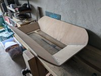
So made use of my spare time this weekend making a rough prototype box which I'll finish off this week when wadding and connectors arrive. Was good to get to know the plans and I'll definitely build a proper pair on a table saw in the new year and get a reference mic.
It’s a bit wonky and not quite the real deal but sounds well enough to keep us going for the time being.


It’s a bit wonky and not quite the real deal but sounds well enough to keep us going for the time being.

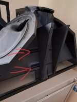
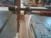
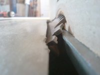
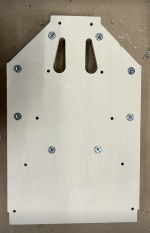
Ok Im getting close to a finished horn now after many failed efforts! One for the printer posse though... What tool did you use to tighten these recessed screws when fitting the halves together? Im off to buy a 90 degree ratchet or something but it seems very cramped to fit something in there 😬We did glue the halves together as well. Lotsa screws and a little glue on the box seams.
Attachments
Leaving the grill frame "naked" won't hurt the response, but eliminating the transition will.
Hi,Reminds me of a Cabinetmaker test I did for a shop years ago.
There is a national museum in Ottawa Canada. Used to be called the Museum of Civilization. I helped make many of the reproductions there.
The test to get hired was to make a hollow pyramid. With joinery on the interior as good as joinery on the exterior. They specified the base dimensions and the height dimensions.
Took me 4.5 hours.
Will always remember it, because it was a real test of what you can or cannot do.
This speaker has many of the same elements.
So I will share a little trick.
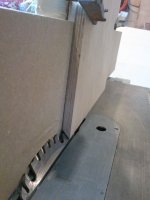
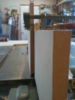
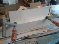
If you need to cut a secondary angle on the edge of boards. Such as the top and bottom boards of the horn in this example you can do it like this.:
https://drive.google.com/folderview?id=0BxsgqQl3NiLuTmxxdzFZaGtneGM&usp=sharing
The pics are in this file. I showed this little trick to someone a while back.
It requires a sacrificial fence, the MDF board with the wooden hook and wingnut in it.
And a little patience in setting up the angle and saw blade junction which is cut into the sacrificial fence a bit.
It allows you to put an angles secondary cut into any shape you choose. Even a convex round if you are patient with it.
Yes, yes - a very old post. But I wonder if you still perhaps have the photos which were previously in the google drive link? The link is now dead / expired unfortunately, but I am very curious to see your trick!
See if you can figure it out.
This allows very acute angles to be cut, and still do it safely. Top clamps are clamping a guide board to the board that you are cutting so that it doesn't drop into the blade as you finish the cut.
This allows very acute angles to be cut, and still do it safely. Top clamps are clamping a guide board to the board that you are cutting so that it doesn't drop into the blade as you finish the cut.
Attachments
-
 2011-01-17 10.39.29 (Large).jpg138.7 KB · Views: 156
 -
 2011-01-17 10.39.13 (Large).jpg136.6 KB · Views: 140
 -
 2011-01-17 10.38.56 (Large).jpg248.1 KB · Views: 136
 -
 2011-01-17 10.38.45 (Large).jpg267.1 KB · Views: 151
 -
 2011-01-17 10.37.36 (Large).jpg154 KB · Views: 155
 -
 2011-01-17 10.37.36 (Large).jpg154 KB · Views: 157
Wow ! this thread is still rocking and progressing!
Art: At this point it seems like 3D printing this design is a thing now, and its making me wonder if your design still needs to be based on its original plywood construction method? For example can you see any benefits of having more organic fiberglass type bevels in the horn etc, now that this new medium is taking hold?
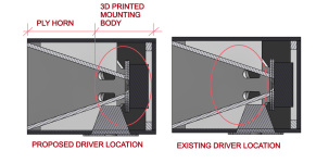
It would be really cool to see if there was a way to gain some construction efficiency, by 3D printing only a "central" assembly or "body" where all the drivers are attached, then transition to ply horn flairs, large or small versions.
Is there any restriction to the "length" of the phase plug exit path? For example if the length became long enough to effectively be called a "tube" or port if you will.. would there be a negative impact?
If not, then the LF drivers could be pushed back in depth, in the cabinet, and a central assembly could be printed more efficiently. IDK just a thought
Art: At this point it seems like 3D printing this design is a thing now, and its making me wonder if your design still needs to be based on its original plywood construction method? For example can you see any benefits of having more organic fiberglass type bevels in the horn etc, now that this new medium is taking hold?
It would be really cool to see if there was a way to gain some construction efficiency, by 3D printing only a "central" assembly or "body" where all the drivers are attached, then transition to ply horn flairs, large or small versions.
Is there any restriction to the "length" of the phase plug exit path? For example if the length became long enough to effectively be called a "tube" or port if you will.. would there be a negative impact?
If not, then the LF drivers could be pushed back in depth, in the cabinet, and a central assembly could be printed more efficiently. IDK just a thought
SynTripP horn 3d printing is certainly a thing thanks to Mr Speakers but for me at least its not been an easy thing with a budget home printer setup. I've found it quite challenging and expensive to tune and run - probably a lot harder than I realised. It also takes over three days to print a half so its reasonably inefficient as I think Mr Speakers warned at the outset all those posts ago. So the idea of more economical use of materials while allowing printed shapes which are harder to make in wood is pretty appealing.way to gain some construction efficiency, by 3D printing only a "central" assembly or "body" where all the drivers are attached, then transition to ply horn flairs
There are some very clever and resourceful folk on this thread, not least the talismanic Art Welter, so I imagine anything is possible. 🙂
Last edited:
The SynTripP two part conical expansion was based on relative ease of build with the relatively good polar response.Art: At this point it seems like 3D printing this design is a thing now, and its making me wonder if your design still needs to be based on its original plywood construction method? For example can you see any benefits of having more organic fiberglass type bevels in the horn etc, now that this new medium is taking hold?
Printed designs could be made with curved profiles with smoother and more even polar response.
I think combinations of 3D print, plywood and "bendy ply" could give the best performance/$$/ease of construction ratio for DIY MEH builds.
Examples of profiles:
https://www.diyaudio.com/community/...he-easy-way-ath4.338806/page-533#post-7131988
Pipe resonances as a negative impact come to mind, though I'm not sure I understand what advantage you are looking to achieve.Is there any restriction to the "length" of the phase plug exit path? For example if the length became long enough to effectively be called a "tube" or port if you will.. would there be a negative impact?
Art
The thought was if the woofers were moved back in the cab, then there would be less area to print. All of the tricky parts could be centralized and printed, and ply added for the horn and braces.
I dont have a top section view, but I believe that if the drivers were moved back it would require the phase plug openings to be extended in length, in order to fit the drivers around the CD.
As of now people are talking about days of printing LOL not hours..
These are brave folks putting the printing time in, but I cringe when I see a giant brace slab being printed. Would love to see "pockets" in the print that accept 90d ply ends for skillsaw simplicity of wood working, and have some kind of nice threaded inserts for easy wood to plastic interface assembly.
At what length and shape does a phase plug opening become a resonating port? And how to prevent that or even use it to your advantage?
Im a sub-amature so take all this with a grain of salt..
Attachments
I think you should print it like in this thread:
https://www.diyaudio.com/community/threads/3d-printing-1-2-of-a-waveguide.307434/
I have successfully printed the horn from that thread and I can't see why you can't print this horn the same. It is simple these days to cut an object in half in any slicer. The only consideration is you need to remove the braces from the inner horn and either cut them from wood or print them separately to avoid using supports. I think I provided the very file needed in this thread somewhere a couple pages back . I'm pretty sure the one I posted already had the braces removed.
The port length, cross section, inlet and outlet shape, enclosed volume between the cone and port exit all affect the acoustical bandpass and resonant frequencies created.At what length and shape does a phase plug opening become a resonating port?
Model the behavior, test, compare to the model. Eliminate what you find disadvantageous, use what you find advantageous.And how to prevent that or even use it to your advantage?
Simple as that 😉
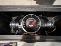
Thought I'd do a photo dump 🙂
The weather has decided that it was a terrible time to make measurements, but I'll get there!
The weather has decided that it was a terrible time to make measurements, but I'll get there!
Attachments
After reading through this thread it seems to me that the limiting output factor seems to be missing excursion for the woofers?
Could the B&C 10ndl64 help solve that problem?
Tried to simulate in Hornresp, but i just started with that and everything i am simulating seems quite a bit off from everyone else so i have to put in some more time with that.
I want to build 2 Synergy style horns in the Winter and the SynTripP seems to tick pretty much all the boxes. Just thinking if it can be pushed a little more with different Woofers so i don't find myself hunting for output once i am used to it with the "standard" loading.
The algorithm found this for me.
Is the Danley patent expired?
Does anyone have any idea/tutorial on how to simulate multiple entry horns in software?
Sorry if it's a silly question 🙄
Hope everyone is having a nice day!
If you are making it for yourself the answer is there never was a reason for you to not make one. Patent protection does not cover self-made, not for sale copies. Second side of the question was the Danley patent unique? was there prior art? Were there prior patents? Yes there were. What Tom managed to get patented was a particular aspect of the idea. He is a very intelligent designer. A well thought out method of integrating multiple drivers into a true point source.Is the Danley patent expired?
Hornresp is a software program used to simulate multiple entry horns.Does anyone have any idea/tutorial on how to simulate multiple entry horns in software?
I walked through the help area in HR but couldnt quite figure out where the taps were being placed and so on.
You can read the 'Multiple Entry Horn Wizard' and 'Two-Way or Three-Way Multiple Entry Horn' sections in the Hornresp Help file for further details.
Appreciation Post
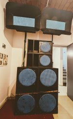
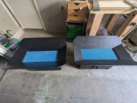
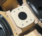
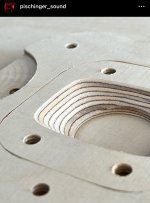
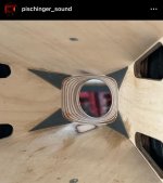
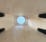
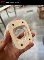
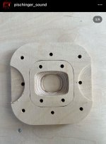
With no synergy speakers available in Barcelona at the time (end of 2022), I tried to build a pair.
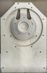
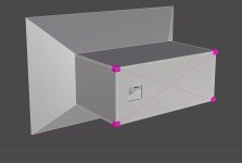
I modelled the 3d in Grasshopper, which saved quite time when making adjustments.
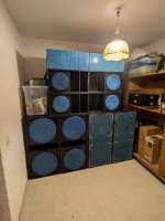
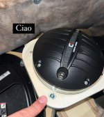
After long hours of tinkering, I finally completed the pair.
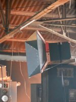
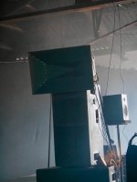
When my friends organized a 10-hour music event, we played them, along with a borrowed 18-inch subwoofer. Genres were bouncing around bass, dubstep, dnb. The speakers’ directivity and fidelity were remarkable, even in a large, reverberant, acoustically horrible warehouse. The sound was just so real, dynamic, present yet effortless. Eh.. Wow...
Thanks Art!
I am massively thankful and inspired by your sharing!
I couldn’t have done it without the energy that dwells in this thread.
PS
For those interested, I’ve organized posts into a set of instructions per speaker part. Feel free to explore:
Speaker Assembly Instructions
There is more process documentation here too:
https://www.instagram.com/pischinger_sound/
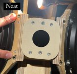
The hardest modelling part for me was the TAP so a couple more pics on it.
Cheers,
Paweł
With no synergy speakers available in Barcelona at the time (end of 2022), I tried to build a pair.
I modelled the 3d in Grasshopper, which saved quite time when making adjustments.
After long hours of tinkering, I finally completed the pair.
When my friends organized a 10-hour music event, we played them, along with a borrowed 18-inch subwoofer. Genres were bouncing around bass, dubstep, dnb. The speakers’ directivity and fidelity were remarkable, even in a large, reverberant, acoustically horrible warehouse. The sound was just so real, dynamic, present yet effortless. Eh.. Wow...
Thanks Art!
I am massively thankful and inspired by your sharing!
I couldn’t have done it without the energy that dwells in this thread.
PS
For those interested, I’ve organized posts into a set of instructions per speaker part. Feel free to explore:
Speaker Assembly Instructions
There is more process documentation here too:
https://www.instagram.com/pischinger_sound/
The hardest modelling part for me was the TAP so a couple more pics on it.
Cheers,
Paweł
Attachments
-
 Zrzut ekranu 2024-11-02 215007.png1.5 MB · Views: 777
 -
 IMG_1741.jpeg28.1 KB · Views: 191
 -
 IMG_1740.jpeg201.9 KB · Views: 183
 -
 IMG_1739.jpeg154.3 KB · Views: 167
 -
 IMG_1738.jpeg118.8 KB · Views: 163
 -
 IMG_1737.jpeg276.1 KB · Views: 177
 -
 IMG_1736.jpeg221.3 KB · Views: 184
 -
 IMG_1733.jpeg102.3 KB · Views: 176
 -
 IMG_1732.jpeg201.8 KB · Views: 164
 -
 IMG_1731.jpeg430 KB · Views: 204
 -
 P1680045.JPG486.4 KB · Views: 233
 -
 P1680010.JPG363.4 KB · Views: 238
 -
 Zrzut ekranu 2024-11-02 215039.png1.2 MB · Views: 246
- Home
- Loudspeakers
- Multi-Way
- SynTripP: 2-way 2-part Virtual Single Point Source Horn