What do you mean by extras? Everything there is for a reason. I think this design is also optimized for LM1875 chip amplifier. On the ther hand BRIAN GT designs are minimalistic nonsense! For a good LM3886 amplifier you need almost all 'optional' components."I’d like to give it a try since your PCB seems to have more extras compared to the BrianGT PCB I have a bunch of"

A lot of LM3886 board designs omit the local decoupling or parts of it. That's a recipe for disaster. In addition, if you want the best performance near clipping you really need to add an RC across the feedback resistor. That's shown in the AC Test Circuit #2 in the data sheet for the LM3886.
Tom
Tom
Here is a board design which is verified to work.
https://www.diyaudio.com/community/threads/ebay-mono-lm1875-kit.341675/page-23#post-6035218
Post #451.
Built and tested, works and sounds great.
https://www.diyaudio.com/community/threads/ebay-mono-lm1875-kit.341675/page-23#post-6035218
Post #451.
Built and tested, works and sounds great.
H
HAYK
Pass one of these music (YouTube ok) and hear if you get it distorted.Hi
I have recently finished building this amp. I really enjoyed it, thanks to all the folks involved in the design of the PCB. I really like the fact that Tom had worked on that design, I’m aware that these IC can be fussy with PCB layout.
Is there a similar thread, meaning an open source layout but this time for the LM1875 ?
I know it’s an old chip but I’ve got a bunch which are at least 20 years old…
Thanks
Eric
Happy together, Turtles.
Sing sing sing, B Goodman.
Requiem of Verdi about 10mn from the start.
If it doesn't sound right, pull up the large decoupling capacitors and put them back with grounding leads tide on air grounded by a resistor about 1 ohm.
Actually, just run it to clipping with a sine wave and 4 Ω load. Watch the output on an oscilloscope as the amp enters clipping. Then pull the decoupling and watch what happens.
Tom
Tom
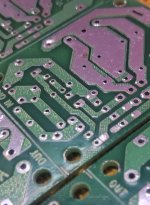
This design is one of the best & i hve bunch of these pcb (Not Chinese made but made in INDIA 🇮🇳). It's inspired by Silicon chip magazine article on LM1875.Here is a board design which is verified to work.
https://www.diyaudio.com/community/threads/ebay-mono-lm1875-kit.341675/page-23#post-6035218
Post #451.
Built and tested, works and sounds great.
Some components are different but very very similar overall."I’ll verify it before I submit to the PCB house."
Attachments

Thanks everyone, appreciated 👍
PCB (5x) were ordered, I will also add the RC across the feedback resistor.
BR
Eric
PCB (5x) were ordered, I will also add the RC across the feedback resistor.
BR
Eric
Well, I have to disagree with you guys. Tom is a well respected person on this forum.
Not only that, he certainly knows what he's doing and just gave you great advice for totally free.
Can't blame the guy (or any other company) for asking a price that apparently people are willing to pay for.
I totally understand if you disagree and get frustrated with certain product prices.
But those are totally different things.
The unfortunate obvious answer to that is, start making (and selling) your own alternatives. 🙂
I agree that the price is little high for many diy enthusiasts but the truth is you get what you pay for!
That's flat-out false. You can ignore my comments if you wish. That's your choice.@tomchr is not a member on this website, he is a vendor hence customer to be served by the administration. He sells lm3886 PCB for about $35, he is certainly not on this thread for the good of the subject and see his sales vanish, his only purpose here,is to poison it to get evantual diys as customers.
This why ignor all his comments.
Anyone can read my participation in this thread and judge for themselves. I've participated since it started in 2018. I have never seen a measurable drop in sales from a thread like this, so I'm utterly un-concerned with its existence. While I obviously won't give away my designs, I am choosing to participate in these threads to better the quality of the project and to help with OP's success.
Actually, I performed the experiment in Post #406 by accident once. That's where I have my experience from. In that specific experiment I had inadvertently reduced the 10 uF decoupling capacitor to 2 uF. I drove the amp to clipping with a 4 Ω load and watched it oscillate near the peak output power.Read #406, this is nothing but an imaginary experiment by an ignorant of the basics of electricity or just to convince a stupid. The impedance of the supply by 10,000uF reservoir linking the chip with 0.1-0.2 ohm wire is the dominant. The 470uF to be as low, it needs over 2.5khz for rectified currents and it will decrease the 0.2 ohms to 0.14ohm. Who is that stupid to convince.
I suggest you measure the impedance of that 10000 uF capacitor. I did that in college many years ago. I found (and you will too, if you bother to measure) that its self-resonant frequency is on the order of a few MHz at the most. That means the supply capacitor behaves inductively at frequencies where the LM3886 still has gain. That results in instability. As noted in the part of the data sheet that you quoted, you need to have a local bypass capacitor of 10 uF (min) with 0.1 uF (min) in parallel right by the IC in addition to the (min) 470 uF of bulk capacitance.
Some of us on this forum have real-world experience. I'm happy to share my experience, which is what I'm doing here. But, of course, I can't force anyone to listen.
That statement makes no sense.My proposition was just to add a resistor grounding the 470uF capacitors to create reverse current in the supply wires and transform the rectified currents into ac.
Should that only apply to me or should that "rule" also apply to other vendors? If so, that basically means you don't want to see the contributions of Douglas Self, John Curl, John Caldwell, George Anderson (Tubelab), Viet (XRK), Jan Didden, and many, many others, including me. I think these folks bring value to this forum in the form of their real-world experience and willingness to share it. Would you rather be without it?He should be alowed to publish just in BAZAAR section. Oriental department.
Tom
Eww dirty word these daysSome of us on this forum have real-world experience.

(the reality is actually really sad)
You forget one important thing again, we share it for FREEI think these folks bring value to this forum in the form of their real-world experience and willingness to share it.
Last edited:
H
HAYK
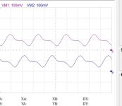
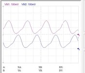
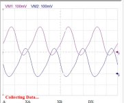
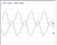
These are the currents of the rails with 0.1 ohm wires and a resistor linking the ground the 2 470uF, from 0 ohm to 1k at 4khz.
Look how the distorted current infecting by radiation the signal, transforms into sine wave.
To propose a new idea for this open source PCB project, I must pass through the judgment of a "respected" vendor of $35 PCB, who has no any conflict of interest according to other vendors.
The website created for fanatics by fanatics has become for vendors to NOOBs.
Attachments

Last edited by a moderator:
H
HAYK
Are you a DIY?That's purely your problem & opinion, no one is forcing you. and i'm certainly not interested on your TASTE.
Anyways, we should get back to our discussion rather than criticizing someone well respected in our forum.
Those "sine waves" are still heavily distorted. I agree that you changed the harmonic structure of the rail currents. But so what? Did it change the output of the LM3886 any?Look how the distorted current infecting by radiation the signal, transforms into sine wave.
Where on Earth do you get that from? Nobody here requires my approval to post about their circuits, including @00940 who started this thread. Or anybody else's approval for that matter. As you also pointed out earlier, you can choose to ignore my posts completely.To propose a new idea for this open source PCB project, I must pass through the judgment of a "respected" vendor of $35 PCB, who has no any conflict of interest according to other vendors.
Tom
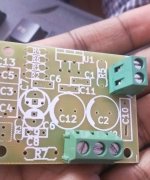
Back to topic, this is my pcb on LM1875 monoblocks. It has multiple options for components. Even SMD on the back side. I never forget to thank my friend who helped me to get these PCBs based on that article.
By the way Tom is a former NatSemi engineer!

I remember a book authored by Late Robert A. PEASE, I liked his teaching style very much. I liked the way he wrote. He truly was a legend. I learned many things from that book. Unfortunately he left us in a very tragic way.
By the way Tom is a former NatSemi engineer!
I remember a book authored by Late Robert A. PEASE, I liked his teaching style very much. I liked the way he wrote. He truly was a legend. I learned many things from that book. Unfortunately he left us in a very tragic way.
Attachments

Last edited:
- Home
- Amplifiers
- Chip Amps
- An open source layout for LM3886?