Question on the Protection board's D5 (TVS diode) - schematic indicates its bi-directional and I am stuck between these two (4A and 11.1A TVS) TVS Diode P6KE110CA Littlefuse and TVS Diode 1.3KE100CA Littlefuse both at Mouser. Hoping someone could confirm if one is a better option, or are they both adequate for this position on the board.
I am a bit late here but I think based on 0940’s prior posts the TVS should have a working voltage slightly above supply rail voltage. For my setup that is around 40V. The part mentioned above seems to have a working voltage that is far too high at 94V. I use a P6KE47CA (40.2V). I believe the purpose of this TVS is to protect the MOSFETs from voltage spikes.
Gregg
D5, the TVS diode, needs to be bi-directional so the part number should end in CA. I believe the voltage for the part you have specified is too high at 171V. You want something with a working voltage slightly above the rail voltage. I am using a P6KE47CA (40.2V).Hey thanks,
This list might be of use to someone.
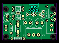
Name Designator Footprint Quantity Manufacturer Part bipolar 10uf C1 E2,5-7 1 UVP1H100MED 1N4148 D1,D2,D3,D4 DO41-7.6 4 1N4148-DIO TVS Diodes D5 P2-15 1 P6KE200A LED5MM LED1 LED5MM 1 Fault indication LED BC546B Q1,Q3 TO92-EBC 2 BC546B BC556A Q2,Q4,Q5 TO92-EBC 3 BC556A IRFB3607 Q6,Q7 TO220BV 2 IRFB3607 100k R1,R5 6,3-2,3 mm 2 22k R2 6,3-2,3 mm 1 22k R3,R4 6,3-2,3 mm 2 220k R6,R8 6,3-2,3 mm 2 8k1 R7 6,3-2,3 mm 1 3k R9 6,3-2,3 mm 1 TLP3906 U$1 SO-6 1 alternative APV1121S 22-27-2021-02 J4 6410-02 1 molex connector
Hello folks. I have finished the Amp recently, but I have a bit of a trouble finding the right input Pot.
I have tried 10k and 100k log pots, but with both the volume gain wasn´t very linear. In fact I am getting about 95 percent of volume gain in first 1/4 of rotation of the pot. And the rest, so about 3/4 quarter of rotation brings almost zero Volume gain.
Am I using the wrong pot? so should I use linear instead of logarithmic? Or am I using wrong resistance?
Thanks,
Adam
You connected it in the wrong direction or ignored ground.
Signal in to the left or right, signal out to amp in the middle and ground to the left over connector.
Quite simple. If it works as you described, change right and left.
100k should work better, as you don't use a buffer on the input. 10k can be too much load for a weak input signal. I would have choosen 50k or none at all.
Thanks a lot for your Answer.
I am pretty sure I have connected it as you described. I have tied the ground(left) pins of the pot and both in and out grounds all together. Could this be a problem?
I could try 50k, I have it on hand, but I don't want to be rotating pots, before I know , I am not doing some basic mistake.
Regards
Adam
Why don't you simply reverse the right and left connection? If it is a log potentiometer and acts as you describe, you got it wrong. There are only two possible ways to connect it...
I see. I could try. But would that just reverse the action of the volume knob? I mean changing it from clockwise to anticlockwise?
Thanks a lot
Adam
Thanks a lot
Adam
No, you have not realized how a log pot works- at one side it's resistance increases slowly and the very fast. Which matches the way spl level rises with voltage.

Hi! I am going to take a jump on the first DIY amp. Can someone please advice whether to build 0094 or chipam.com version of LM3885 board? What are the main differences between these 2 designs? Thanks for the answers in advance!
i just finished soldering, but too much hum occured, so what should i do to get rid off this.I just finished my version of the Super Gain Clone stereo amp board. It places the rectifier and two channels on a single PCB.
GitHub - profdc9/SuperGainClone: A stereo layout of Bob Cordell's Super Gain Clone amplifier.
You can download the whole project, kicad, gerbers, and all using the Download button. I have a picture of my build below.
Hello guys,
probably a stupid question, but I am building a second pair of these modules and I was short on 09-c12 470uf Caps. For some reason Mouser sent me a different type caps - HW(m) instead of HE(m). Both are the same values(cpacity, temp, voltage) as far as I can see, it´s only the size is a bit different.
is it ok to mix these together? for example put two of each on each module. could there be any problem with this?
I don´t want to order these again. it´s too much of a hassle.
Thanks a lot,
adam
my mistake, poor connection on input ground. thanksi just finished soldering, but too much hum occured, so what should i do to get rid off this.
Hi
I have recently finished building this amp. I really enjoyed it, thanks to all the folks involved in the design of the PCB. I really like the fact that Tom had worked on that design, I’m aware that these IC can be fussy with PCB layout.
Is there a similar thread, meaning an open source layout but this time for the LM1875 ?
I know it’s an old chip but I’ve got a bunch which are at least 20 years old…
Thanks
Eric

Hi,
Very nice work, you thought of everything.
I’d like to give it a try since your PCB seems to have more extras compared to the BrianGT PCB I have a bunch of.
Do you still have the Gerbers and would you share them?
Thanks
Eric
Very nice work, you thought of everything.
I’d like to give it a try since your PCB seems to have more extras compared to the BrianGT PCB I have a bunch of.
Do you still have the Gerbers and would you share them?
Thanks
Eric
- Home
- Amplifiers
- Chip Amps
- An open source layout for LM3886?