Hi, thanks for the answer!
I've got ferrit rings and already use those on the power cables. Would this work on the signal cables, too?
I've got ferrit rings and already use those on the power cables. Would this work on the signal cables, too?
Hi clueless , if you have a new Phone check if it has bluetooth 5.0
is so it is likely you can pair it with two receivers nat the same time in which case you could use one for each speaker. since bluetooth 5 has much better transmission than previous versions you might get a better sound without cables.................
Bluetooth Kernspezifikation Version 5.0 Funktionsubersicht | Bluetooth(R) Technology Website
Heya guys, I'm having some issues with the DC & PSU files I cannot get them to upload to JLC has anyone got gerbers for them as they seem to work?
Did you try the latest files, in post 235 ? https://www.diyaudio.com/forums/chip-amps/321922-source-layout-lm3886-24.html#post6470137
They upload just fine with JLCPCB on my side. Beware that I also provide the eagle source files, which will not work. Take the zip called gerbersXXX
They upload just fine with JLCPCB on my side. Beware that I also provide the eagle source files, which will not work. Take the zip called gerbersXXX

Did you try the latest files, in post 235 ? https://www.diyaudio.com/forums/chip-amps/321922-source-layout-lm3886-24.html#post6470137
They upload just fine with JLCPCB on my side. Beware that I also provide the eagle source files, which will not work. Take the zip called gerbersXXX
Ahhh I completely missed that post tried finding it but dyslexia took over!
Thanks bud!
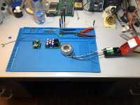
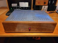
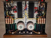
Over the weekend I managed to build out the amp and power supply with no issues other than having to learn about what a snubber is. I am new to the audio world so this has actually been fun. Am attaching pics of my build.
For 00940 - I am so new to this all I don't understand how to size the DC protect TVS... I am using a 42VAC transformer (21VAC CT). Should the TVS be on the order of 60V or 30V?
Gregg
For 00940 - I am so new to this all I don't understand how to size the DC protect TVS... I am using a 42VAC transformer (21VAC CT). Should the TVS be on the order of 60V or 30V?
Gregg
Attachments
If you have a 2x 21 volt (AC) transformer, you should see around 2x 30 volt DC at the power supply. So you have +30V / 0V /-30V to feed your amp.
I am seeing +30.8V / 0V / -30.8V unloaded with it dropping under load. The question I am asking is what size should the TVS diode be for the DC protect board. After doing a bunch of reading, I now believe it should be a 33V bi-directional TVS. Is my conclusion correct?If you have a 2x 21 volt (AC) transformer, you should see around 2x 30 volt DC at the power supply. So you have +30V / 0V /-30V to feed your amp.
What DC protection are you talking about? The LM3886 does not need one. If you get a real one, it is the best protected amp chip ever build. Or do you want to keep the transformer DC free? That is a very critical part as you deal with grid voltage and not necessary for the amps function. A mistake will blow up the capacitors like large fire crackers...
The board that is part of this thread. I recognize it is probably overkill, but am building it as part of educating myself about all the things around audio amplifiers. You can find the details here in this same thread: https://www.diyaudio.com/community/threads/an-open-source-layout-for-lm3886.321922/page-7
Regardless of if I am wasting my time understanding and building the board for use with the LM3886, I want to understand how to properly size the TVS diode. The protect board sits between the LM3886 and the speaker so we aren't dealing with mains level voltages.
Gregg
Regardless of if I am wasting my time understanding and building the board for use with the LM3886, I want to understand how to properly size the TVS diode. The protect board sits between the LM3886 and the speaker so we aren't dealing with mains level voltages.
Gregg
Sorry, I missed this quite useless board and can not help you with the diode. The (real, not faked!) LM3886 is practically bullet proof. Even shorts under load and one supply voltage missing do not harm it. In fact, this is a test for fakes, as these usually do not stand such treatment. Anything in the path from amp to loudspeaker degrades sound and should be avoided.
@bozoc: sadly that heatsink didn't fit. Not wide enough for the diode bridge 🙁
@Lingwendil: yes, that's worth a try. On 2 layers boards, their cost of shipping is actually a bit higher than smartproto, so the final price is about the same.
Anyway, here are two auxiliary pcb. One is the PS (60*100mm), one is a simple DC protect (60*40mm). Eagle files in the zip. There's a small error to correct on the ps, the top molex connector should of course be labeled v- and not v+.
Really nice project, this one!
I have a question about the schematics of the power supply. It looks like there is a snubber capacitor and RC snubber that were connected before the rectifier bridge. On the official PDF from TI they have hose placed after the rectifier. Why was it placed before in this project?
Thank you,
Pavlo
Question on the Protection board's D5 (TVS diode) - schematic indicates its bi-directional and I am stuck between these two (4A and 11.1A TVS) TVS Diode P6KE110CA Littlefuse and TVS Diode 1.3KE100CA Littlefuse both at Mouser. Hoping someone could confirm if one is a better option, or are they both adequate for this position on the board.
Also, is there a maximum supply voltage, power rating for this protection? Since it's in a LM3886 thread, is it still adequate for a 150-200w amplifier build?

Also, is there a maximum supply voltage, power rating for this protection? Since it's in a LM3886 thread, is it still adequate for a 150-200w amplifier build?
Question on C1, on the schematic it is a polarized capacitor, however through this thread there is mention that C1 needs to be bi-polar? Hoping someone could explain and confirm which is correct.
Can you elaborate as to the "why" - since it shunts to ground? I thought bi-polar was only if it was in the direct signal path? Just trying to understand better the schematic and help me apply to amplifiers in general.Bipolar, like the signal.
A bipolar capacitor by definition can have either polarity of voltage across it,
and still function properly.
A capacitor connected to ground could still have either polarity of signal across it,
depending on the circuit used, such as this one. Shunt parts are definitely in the signal path
as much as series parts are. Think of a voltage divider, for example.
Some believe that a polarized capacitor can be used for AC signals if the reverse voltage is small.
This is not a good idea.
Last edited:
- Home
- Amplifiers
- Chip Amps
- An open source layout for LM3886?