thanks for the explanation. I looked at a few other amplifier schematics and you are correct, they seem to all use a bi-polar cap, what confused me is most use a film capacitor, which by nature is bi-polar. I think in this design, the electrolytic is used strictly because of space restrictions. Luckily I had a bi-polar sitting around, so I installed that in place of the one I ordered. I will start with some testing on the protection board, before placing it into full-time use.
You can use a polarized capacitor (connected in either series or shunt), if there is enough DC voltage bias
on it so its polarity will never reverse. For example, used as an output DC blocking capacitor in a single ended circuit.
on it so its polarity will never reverse. For example, used as an output DC blocking capacitor in a single ended circuit.
Has anyone built and used this protection circuit in a build? I build one (only substitution on BOM is MPS42/92 for the BC546/556 - reversed orientation on board), but when I power up it seems to be working in the opposite of what I think should be normal operation - no delay coming on and about a 2-3 second delay turning off. The other issue is I've tried to induce a DC to create a fault condition - nothing happens??? I have tried with DC power voltage to the board of 12-30V and inducing DC on the output from 1.5-9.5Vdc. I get no disconnect from the input to outputs on the board and no fault indicator LED lights.
Any insight on what might be the issue.
Any insight on what might be the issue.
Attachments

So I guess this means no one has made this protection board and got it working? I replaced the substituted A42/A92 for the spec'd 546/5556 and continues to come on immediately, delayed shut off and has not trigger to disconnect either connection to the speaker and the LED does not light. Would appreciate some assistance, anything to try, since I went to the trouble of ordering boards and have a build I was planning these speaker protection. for.
TIA!
TIA!
Speaker Protection is working!!
Unsure if I had a bad solder joint, or if it was all from a faulty LED, but after re-working the solder connections on most of the board and replacing the LED - the protection board is working on my test bench. I have tested with supply voltage of 12-31vDC, while introducing DC on the outputs of 1.5-9.5vDC and it works without any issues. Will take some time to re-work the wiring in my amplifier I had these planned for, I put in other protection boards while I was working through these issues.
Unsure if I had a bad solder joint, or if it was all from a faulty LED, but after re-working the solder connections on most of the board and replacing the LED - the protection board is working on my test bench. I have tested with supply voltage of 12-31vDC, while introducing DC on the outputs of 1.5-9.5vDC and it works without any issues. Will take some time to re-work the wiring in my amplifier I had these planned for, I put in other protection boards while I was working through these issues.
Thinking of constructing a 6-channel amp with this design. Today I have capacitors protecting my tweeters.
Is it possible to modify this design (feedback) integrating a high pass protection?

Is it possible to modify this design (feedback) integrating a high pass protection?
Hi,Has anyone built and used this protection circuit in a build? I build one (only substitution on BOM is MPS42/92 for the BC546/556 - reversed orientation on board), but when I power up it seems to be working in the opposite of what I think should be normal operation - no delay coming on and about a 2-3 second delay turning off. The other issue is I've tried to induce a DC to create a fault condition - nothing happens??? I have tried with DC power voltage to the board of 12-30V and inducing DC on the output from 1.5-9.5Vdc. I get no disconnect from the input to outputs on the board and no fault indicator LED lights.
Any insight on what might be the issue.
Can you please share the link to this speaker protection project?
There’s no link, it is part of this thread, the schematic and gerbers are available in Post #121 if you need them.Hi,
Can you please share the link to this speaker protection project?
Me too in India and keen to build this. Im actually looking for something that includes the speaker protection.I was intending on getting them done from JLCpcb, but shipping period and charges have increased a lot due to current pandemic. So will etch pcbs.
If you could guide about connection between layers, how to stitch them.
Ping me I have some local contacts who deliver in a week and their prices are on par with JLPCB. So no customs duty.
Im in Bangalore. But my PCB guy is in Pune. And one guy is in Gujarat.
Can you pls PM me Pune guy's contact detailsMe too in India and keen to build this. Im actually looking for something that includes the speaker protection.
Ping me I have some local contacts who deliver in a week and their prices are on par with JLPCB. So no customs duty.
Im in Bangalore. But my PCB guy is in Pune. And one guy is in Gujarat.
Just finished a build using these boards. Paired them with an old 18vac transformer and some spare chipamp.com PSU boards I had. Been listening to it all morning at work. Sounds great.
Thanks 00940 and everyone else.
Thanks 00940 and everyone else.
@bullittstang I'm going to put together a pair of speaker protection boards and use them on another project. Glad to hear at least one other person has made 'em and they work 😀
I also wanted to build this but i can't find any complet BOM for DC protect or the PSU. If anyone could share it it would be great.
On page 13 there is some information but it seems incomplete.
On page 13 there is some information but it seems incomplete.
@intakto I believe there is a pretty barebones parts list in the project files but it'll just have values IIRC.
Here are the parts I ordered from mouser for the protect board:
https://www.mouser.com/ProjectManager/ProjectDetail.aspx?AccessID=81a9380f94
I may have ordered extras of a few things in there. Can't remember exactly. Everything works great tho. Super happy with it.
I used a different PSU so can't help there. I reckon there would something with the values needed in the build files.
Hey thanks,
This list might be of use to someone.
This list might be of use to someone.
| Name | Designator | Footprint | Quantity | Manufacturer Part |
| bipolar 10uf | C1 | E2,5-7 | 1 | UVP1H100MED |
| 1N4148 | D1,D2,D3,D4 | DO41-7.6 | 4 | 1N4148-DIO |
| TVS Diodes | D5 | P2-15 | 1 | P6KE200A |
| LED5MM | LED1 | LED5MM | 1 | Fault indication LED |
| BC546B | Q1,Q3 | TO92-EBC | 2 | BC546B |
| BC556A | Q2,Q4,Q5 | TO92-EBC | 3 | BC556A |
| IRFB3607 | Q6,Q7 | TO220BV | 2 | IRFB3607 |
| 100k | R1,R5 | 6,3-2,3 mm | 2 | |
| 22k | R2 | 6,3-2,3 mm | 1 | |
| 22k | R3,R4 | 6,3-2,3 mm | 2 | |
| 220k | R6,R8 | 6,3-2,3 mm | 2 | |
| 8k1 | R7 | 6,3-2,3 mm | 1 | |
| 3k | R9 | 6,3-2,3 mm | 1 | |
| TLP3906 | U$1 | SO-6 | 1 | alternative APV1121S |
| 22-27-2021-02 | J4 | 6410-02 | 1 | molex connector |
For the psu i garhered this.
As far as snubber networks go neurochrome notes that it is an exercise in futility as it makes not impact on performance. Most of the designs use 1 ohm but in the rectification and snubbers article, 10 ohms was used so it was also highlighted that exact values are not critical. For 150nf let's say a 6.8ohm resistor can be used. I am starting from 0 on this so i have no left over psu or anything 😉
PCB holes for KBU package B2 25A/400V KBU2504-G or the 15A/400 GBU15G. PCB holes for GBU4 package B3 Aluminium Electrolytic Capacitors C1,C2,C3,C4,C5,C6,C7,C8 50volts 2200uF 18x35.5 20% 7.5LS Film Capacitors 0.01uF 100volt 10% RoHS Compliant C9,C10 C050-025X075 Film Capacitors 0.15uF 63volts 10% RoHS Compliant C11,C12 C050-025X075 Terminals 250 PCB TAB J1,J2,J3,J4,J5,J6,J7,J8,J9,J10 F061.100 LED5MM LED1,LED2 LED5MM R-EU_0309/V R1,R2 ** Metal Film Resistors - Through Hole 1/2W R3,R4 8.06Kohms 1% should be ok depends on rail voltage OHMITE-RA-T2X Heatsink OHMITE-RA-T2X later posts suggest Ohmite RA-T2X-38E 22-27-2021-02 J11,J12 molex connectors MKDSN1,5/2-5,08 X1,X2,X3,X4,X5
As far as snubber networks go neurochrome notes that it is an exercise in futility as it makes not impact on performance. Most of the designs use 1 ohm but in the rectification and snubbers article, 10 ohms was used so it was also highlighted that exact values are not critical. For 150nf let's say a 6.8ohm resistor can be used. I am starting from 0 on this so i have no left over psu or anything 😉
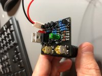
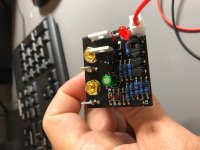
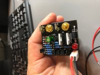
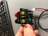
Started the builds. This is the first one i fitted the coil in. I am still waiting for some parts but it strats to look good. Forming the colis was interesting.
- Home
- Amplifiers
- Chip Amps
- An open source layout for LM3886?