Thank you for these wise words, that's exactly what it's all about.It is a matter how much work to put into it.

I would hope that a preamp has at least 10 dB output voltage margin, i would say preferably a little more,@wahab
Marginal correction:
sqrt(25*8) = 14.14Vrms
14.14/9.333 = 1.52Vrms = 2.144Vpeak
Such a small thing is super easy task to limit.
🙂
but even with only 10 dB it would be capable of 4.5V RMS.
FTR an op amps based preamp has at least 7-8V RMS output level capability.
That's all true - and we all know what we need a preamp for these days.
#
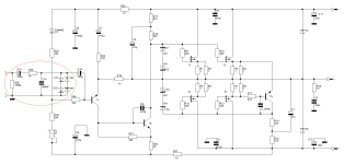
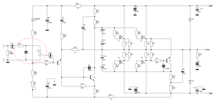
Let's think again very quickly, but not deeply, more with the gut (everything else goes beyond my propagated DIY-Communication style ) - and look at the schematic below.
But, a deeper look at the world-famous schematic of the NAD3020i expands our options dramatically - we can steal a little something from there.
Disclaimer of liability:
my brain is still on standby
regards,
HBt.
Small print - "das Kleingedruckte":
Well, yes,
the 25 watt figure in the thread title is to be understood as an advertising statement - another cat leaves the bag.
#
Let's think again very quickly, but not deeply, more with the gut (everything else goes beyond my propagated DIY-Communication style
) - and look at the schematic below.But, a deeper look at the world-famous schematic of the NAD3020i expands our options dramatically - we can steal a little something from there.
Disclaimer of liability:
my brain is still on standby
regards,
HBt.
Small print - "das Kleingedruckte":
Well, yes,
the 25 watt figure in the thread title is to be understood as an advertising statement - another cat leaves the bag.
Attachments
Interesting "solution", but i would observe that if a car has a tire that is flat it s not by increasing the pressure
on the remaining ones that the problem can be solved...
on the remaining ones that the problem can be solved...
I would hope that a preamp has at least 10 dB output voltage margin, i would say preferably a little more,
but even with only 10 dB it would be capable of 4.5V RMS.
Gain of the PowerAmp. :
is now 3 equal 10dB for fullscale!
FTR an op amps based preamp has at least 7-8V RMS output level capability.
is now 1.83 equal 5.4dB for fullscale!
Or to put it another way:
we need operating voltages of +/- 105Vdc for the headroom you require - "für die von Dir geforderte Übersteuerungsreserve"!
Interesting comparison, really fitting.but i would observe that if a car has a tire that is flat it s not by increasing the pressure
on the remaining ones that the problem can be solved...

Since the matter is too stupid for me right now, here is one last example to outline the extent:
We all know that our CDP can deliver an amplitude of 2.83Vp (of course its operational amplifier, part of the reconstruction filter, could theoretically be driven up to +Vcc-2Vdc, but let's stick to a maximum of 2.83Vp) -> our preamp could amplify this voltage 10 times (that's why it absolutely needs now rails of +/-31Vdc) -> our stupid output stage, the PowerAmp, now amplifies this 28.3Vp also 10 times -> 283Vp.
If we follow your argument of absolute safety, then all audio power amplifiers would need to be 5000W_rms types.
Dear wahab,
can we please stop this **** from now on, i.e. Schmu - "den Schmu sein lassen" - and stay in reality(?).
kindly and bye,
HBt.
You dont get that the problem exist only for this kind of topoogy and not for differential IPS, and that those latter
can endure whatever input level with no consquences for the amplifier..?..
A differential IPS output current is limited by a current source that provide at most a few mA to drive the VAS, while
those pseudo-CFAs have unlimited IPS output current, actually only limited by the emitter degeneration resistance
that is 120R in your exemple, so theorically up to 200mA IPS peak output current to drive the VAS base.
And since we re talking preamps i still have a 1979 Akai PR 04A whose high voltage op amps are fed with +- 30V,
so it s capable of roughly 15V RMS output signal, Akai designed it this way so the RIAA preamps would never
saturate even with 200mV RMS MD pick up signal or 50mV RMS MC pick up signal, because you know, HiFi
is not only a question of noise and THD, that s also a matter of dynamic range.
Now since you seems to have difficulties grasping a few basics i wont make any more interventions, so finish
the design and present your global idea according to your beliefs, who knows, the tossed coin could well
fall on the side instead of one of the faces.
Dear Wahab,
please breathe in and out deeply and calmly ...
Statements like this one do absolutely nothing good for my counterpart. Once again, I'm saying this quite directly.
How do you (will) know what I have up my sleeve?
With respect,
HBt.
Psst.
Please simply submit your alternative circuit proposal, complete - do good.
please breathe in and out deeply and calmly ...
Now since you seems to have difficulties grasping a few basics (...) according to your beliefs (...)
Statements like this one do absolutely nothing good for my counterpart. Once again, I'm saying this quite directly.
How do you (will) know what I have up my sleeve?
With respect,
HBt.
Psst.
Please simply submit your alternative circuit proposal, complete - do good.
Thank you for at least not ... me this knowledge.you know, HiFi
is not only a question of noise and THD, that s also a matter of dynamic range.
I have a real-time thingy flying around here that tells me quite clearly what the average dynamics are in digital audio - it's frightening. Or in the meantime with DAB or ordinary FM radio ..!
Yes, the dynamics 😢.
HBt.
(By the way, my teachers and lecturers are turning in their graves right now)
A differential IPS output current is limited by a current source that provide at most a few mA to drive the VAS,
So I wouldn't give you full marks for this exam answer because it's not quite correct, or does it cover all possible operating cases?
while
those pseudo-CFAs have unlimited IPS output current, actually only limited by the emitter degeneration resistance
that is 120R in your exemple, so theorically up to 200mA IPS peak output current to drive the VAS base.
Well, look again with a little more accuracy, I see R19 = 1000Ohm. From this it follows, over the thumb +/-25mA. Furthermore, I see R16+R17 = 2710Ohm, which also results in +/-9.2mA over the thumb.
Have you really and truly calculated Vcc/R22 ????
speechless,
HBt.
PS
My calculation and therefore the figures are not really correct either, but it illustrates and depicts reality more closely than the moonshine statement quoted.
Addendum
If anyone would like to have a different form of negative feedback and IP (i.e. LTP) , you would be well advised to copy Hugh's AN39 suggestion.
The "Babe and the Bub" have absolutely nothing against it.
A differential IPS output current is limited by a current source that provide at most a few mA to drive the VAS, while
those pseudo-CFAs have unlimited IPS output current, actually only limited by the emitter degeneration resistance
that is 120R in your exemple, so theorically up to 200mA IPS peak output current to drive the VAS base.
That s clear enough methink.
The current that flow from a transistor collector cant come from elsewhere than from its emitter, and from the path
of smaller resistance that is connected to said emitter.
In AC mode this current will flow through the 120R resistance and through the capacitor that goes to GND,
with a differential the emitters are connected in serial with a current source.
What level do you want to go down to - I feel like I'm in Kindergarten right now.The current that flow from a transistor collector cant come from elsewhere than from its emitter, and from the path
of smaller resistance that is connected to said emitter.
As soon as we want to move on to semiconductor physics, I say:
I'd love to.
But if this **** has to be carried out in the DIY forum, send me a few exercises on the bipolar transistor via PM, which I will then solve atok in a video conference.
Or should I prepare a lecture script on the processes at the PN junction?
Exactly, here the emitter of our input transistor represents a special node, correct ... and further on in the text?In AC mode this current will flow through the 120R resistance and through the capacitor that goes to GND,
And to top it all off, both emitters are connected to each other, a node has been created.with a differential the emitters are connected in serial with a current source.
wahab,
You're trying to beat me in my area of expertise - give it up! Please - give it a rest, I'm fed up with your eternal bickering.
I'm telling you kindly:
this artificial dispute leads to absolutely nothing good, I already realized that in the Stellema thread. My willingness to feed this communication is approaching zero.
HBt.
Those who know what it is about have already made the conclusions, all i said is 100% accurate and can even
be easily checked with a simulator, wich i did btw and wich you didnt, so rather than useless talks here the IPS output
current that get through the VAS base when the input signal is 3.5V RMS in red and 5V RMS in green.
So now good luck in getting the laws of physics obeying your expertise.
be easily checked with a simulator, wich i did btw and wich you didnt, so rather than useless talks here the IPS output
current that get through the VAS base when the input signal is 3.5V RMS in red and 5V RMS in green.
So now good luck in getting the laws of physics obeying your expertise.
Attachments
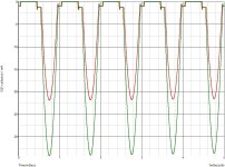
Input /signalsource - voltage:
u1red
= 9.9Vpp
---> need +/- 51Vcc Rails
u1green
=14.14Vpp
---> need +/- 71Vcc Rails
in order to be theoretically controllable - "aussteuerbar zu sein"!
#
Beelzebub can only be legally controlled up to the overdrive limit of slightly more than 40Vpp - that's why the headline says 25Wrms at loads of 8Ohm - and nothing else.
R19 / R22 +1 = 9.333
maximum input voltage of the present amplifier that may have to be limited (basically completely independent of the design of the IP-VA stage) with a gain of 19.4dB
is
20Vp / 9.333 = 2.143 Vp
equal to
1.52Vrms for sinusoidal !
The desired listening level is often set with a voltage divider at the input of the amplifier, often designed as a logarithmic potentiometer.
##
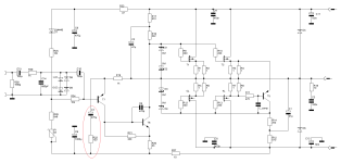
In principle, it is an easy undertaking to saturate (or overdrive) T7 as well ...
but I'm much more interested in the question of why there are more and more users (out there) who are determined to lead innocent readers up the garden path.
Dear reader,
please don't let them do this to you.
u1red
= 9.9Vpp
---> need +/- 51Vcc Rails
u1green
=14.14Vpp
---> need +/- 71Vcc Rails
in order to be theoretically controllable - "aussteuerbar zu sein"!
#
Beelzebub can only be legally controlled up to the overdrive limit of slightly more than 40Vpp - that's why the headline says 25Wrms at loads of 8Ohm - and nothing else.
R19 / R22 +1 = 9.333
maximum input voltage of the present amplifier that may have to be limited (basically completely independent of the design of the IP-VA stage) with a gain of 19.4dB
is
20Vp / 9.333 = 2.143 Vp
equal to
1.52Vrms for sinusoidal !
The desired listening level is often set with a voltage divider at the input of the amplifier, often designed as a logarithmic potentiometer.
##
In principle, it is an easy undertaking to saturate (or overdrive) T7 as well ...
but I'm much more interested in the question of why there are more and more users (out there) who are determined to lead innocent readers up the garden path.
Dear reader,
please don't let them do this to you.

Rl=8Ohm
u1=1Vrms
u2=9Vrms
This corresponds to a real 10W in class A mode of the output stage, now an almost undistorted, sinusoidal collector current (of the input transistor T7) of an incredible 80µA peak to peak flows - says my PSPICE.
With higher input levels, of course, this time function ic(t) is visibly deformed. At the safe level limit it is a 120µA peak to peak flow - or variation.
Now the fantasy story:
u1=3.5Vrms; 5Vrms; 7.5Vrms; 10Vrms; 18Vrms - (sine)
---> ic_span -> 20mA; 30mA; 50mA; 65mA; <100mA the time function can no longer be sinusoidal, which is immediately obvious to anyone who knows what a BJT is.
Even if some statements are fragmentarily halfway correct or even if they should be understood as correct statements, they are mostly meaningless, as there is no object-related relevance.
These are nothing more than interjections, the intention of which is to deliberately disturb and unsettle the conference participants.
HBt.
u1=1Vrms
u2=9Vrms
This corresponds to a real 10W in class A mode of the output stage, now an almost undistorted, sinusoidal collector current (of the input transistor T7) of an incredible 80µA peak to peak flows - says my PSPICE.
With higher input levels, of course, this time function ic(t) is visibly deformed. At the safe level limit it is a 120µA peak to peak flow - or variation.
Now the fantasy story:
u1=3.5Vrms; 5Vrms; 7.5Vrms; 10Vrms; 18Vrms - (sine)
---> ic_span -> 20mA; 30mA; 50mA; 65mA; <100mA the time function can no longer be sinusoidal, which is immediately obvious to anyone who knows what a BJT is.
sure?(...) by the emitter degeneration resistance
that is 120R in your exemple, so theorically up to 200mA IPS peak output current to drive the VAS base.
Even if some statements are fragmentarily halfway correct or even if they should be understood as correct statements, they are mostly meaningless, as there is no object-related relevance.
These are nothing more than interjections, the intention of which is to deliberately disturb and unsettle the conference participants.
HBt.
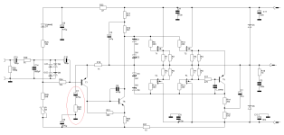
You /user may be well advised to set the output offset and observe the drift behavior in order to identify the correct position /polarity later.In option 3 the capacitor should have opposite polarity.
A test setup can do no harm.
Last edited:
With apodictic (and completely absurd) demanded overdrive reserves of 10dB, I lose all joy in DIY, especially in sharing fun ideas.
What does 10dB mean? Well, the factor 3 appears, so 3 times more. 3*20 = 60 (+5V) Or three portions on top, as 20 + 3*20 = 80 (+5V). Depending on how you want to define or understand this sauce, the required operating voltage / rails increases.
In other words, the headline would better read as:
2.8Wrms with a fabulous overdrive /overload reserve, necessary input voltage 0.5Vrms for full scale / rated power at 8Ohm Load.
Have I been able to express myself clearly?
HBt.
- Home
- Amplifiers
- Solid State
- Beelzebub: 25 Watt for 8 Ohms