So that the ANK can finally continue:
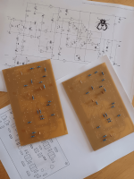
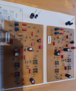
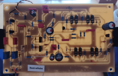
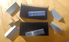
I etched and drilled two circuit boards - used up the last of my base material. But the old photo-coated stuff is now really just scrap. Exposing and developing is a horror ... and my printer is no longer the yellow of the egg either ... but it will have to do for the prototype, the ultimate test setup.
Tomorrow I will continue - then i will gradually show
a) the assembly as "Bub"
b) as "Babe" - with the present layout!
😎

Looking good 👍 are you doing the power supply board yourself as well?
Keep us updated, looking forward to seeing this take shape.
Keep us updated, looking forward to seeing this take shape.
Together, the twins (should be) are the ultimate Alpha-Nirvana-Killers ..!
Reminder:
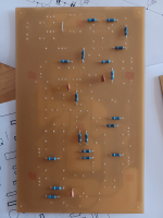
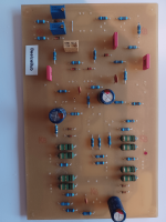
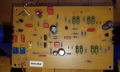
For the time being, the quick circuit board design is still available for the upcoming real test. A marginal error occurred during routing - but it's not really worth mentioning, I'll go into it later.
I didn't have 470nF on hand, so now two 1µ MKTs are blocking.
Reminder:
For the time being, the quick circuit board design is still available for the upcoming real test. A marginal error occurred during routing - but it's not really worth mentioning, I'll go into it later.
I didn't have 470nF on hand, so now two 1µ MKTs are blocking.
Attachments

Regarding the supply -(...) are you doing the power supply board yourself as well?
"everything is still open"
BB_v1
is just the beginning, the sample still has to confirm the simulations ... too much is still missing for a finished ANK ...
greetings,
HBt.

Attachments
The tension increases immeasurably 😱
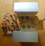
But I need a little creative break - will the beelzebub principle work properly?
The SoftClipper can now be tested
in the same way as the 1st stage /alone without the pushpull sourcefollower!
Now come the moments I want to run away from - @wahab has scared me so much.
?
will it oscillate
run away thermally
burn out
...
Is Babe ultimately better than her brother Bub?
Attachments

If the 1st version of the project does not show any problems, then this design can become a street sweeper in various forms.
Three small circuit boards:
the
greetings,
HBt.
Three small circuit boards:
the
- limiter, softclipper
- front end, various IP-VA stages
- output stage, for example' with the possibility of installing 2* 4 HEXFets and also between large device or TO220 small
greetings,
HBt.
Those self etched old school boards are great, true and only real DIY, keep on the good work.
Last edited:
Progress report
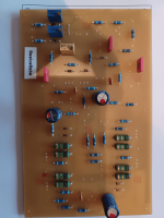
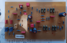
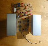
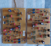
both genders work perfectly! They have passed the first static test. The thresholds of the limiter can be adjusted perfectly. D10 & D9 are ZF4V7 types, T9 is a 2SC2240GR & T10 is a 2SA970GR ... next week I will find time to make two new, up-to-date schematics. For my tests today (without the 2nd stage) I have the output hardwired to GND, 0 volt potential. P1, the 5kOhm trimmer is currently set so that the collector potential of the T6 is automatically set between +3.9V and +5V. For the Babe (the opposite sex) it is -3.9V and -5V.
The combination transistor, made up of T7 and T6 (the first stage), behaves exactly as I theoretically expected when heated by itself or by an external source. This is interesting because a thermal coupling of T7 with T6 (via a heat sink) could compensate for the inevitable drift. At the moment I am assuming that this is the case, i.e. I am placing a common aluminum bracket.
Everything is set to “go”. Now it's the turn of the heat sinks for T1 to T4 ... So please be patient.
Incidentally, the six protective diodes are not a luxury, so they are not superfluous decoration. D6 and D5 are still completely missing from my current layout (I will also revise this slightly if the entire, simple circuit delivers what it promises ...)
I'm trying to “release the fire” soon, but everything can mess up my schedule at the moment. But the signs are good and I will report regularly.
With this in mind, I'm hoping for a plethora of Beelzebuben or Beelzebabes to give the AN39 disciples hell.
To be honest, AN39 doesn't interest me at all - because Lucifer makes his own party 😉.
Greetings,
HBt.
Addendum
No THD miracles are to be expected with the current version 1 - front end. The DIYer must be aware of this. Less than 0.03% would be nice, but if you consider that the MF-A1 is a real 0.5% monster, then everything puts itself into perspective. Incidentally, this is a genuine class A SE stage. The PP class A output stage (unusual only at first glance) is only attached /fitted (but part of the nfb).
Anyone who successfully implements such a simple concept demonstrates courage and true sporting spirit. That's how I see this little amplifier idea. I wish every potential replicator a large portion of joy in the unusual and the old-school principle.
After the first electrical test, I am very confident that everything will also run smoothly in dynamic terms - let's hope for the best.
I will of course provide a BOM as soon as I can give the go-ahead with a clear conscience.
If I end up in the salad, with the ANKproject (an atok design, nothing more), the tomatoes are welcome to fly ... 🙂
kindly,
HBt.
#
P2 & P3 are 10k trimmer
T5 & T8 are BC5xx B or C types
C14 is a FKP one
all three bootstrap cap's are 63Vdc types
T7 still has its own (optional) 51Ohm emitter resistor on the board, it is missing in the schematic
"Dankeschön"Good Luck to you.
Beelzebub is on the way ..
thx
Please stay tuned and enjoy the progress of the project.
HBt.
Little by little
"mühsam ernährt sich das Eichhörnchen"
Before I drill the aluminum angles,
a word about the different genders:
Both variants work in the same way in terms of their external effect; whether they will also perform equally in terms of measurement remains to be proven.
But equipping the existing PCB is child's play. You start from the origin (Adam!) and swap NPN with PNP and PNP with NPN, the same applies to the N-MOS -> P-MOS and P-MOS -> N-MOS. All SI diodes are reversed, all polarized electrolytic capacitors are polarized -> reversed. The operating voltage lines are reversed, i.e. PIN +Vcc is connected to the negative operating voltage and vice versa. Only the limiter, the soft clipper, can be fitted unchanged.
This is how Adam becomes Eve! marked red ...
#
Now I'm going to rest for a few days until I can continue with the project.
Lucifer was commanded by God to talk with Gabriel - and now, unfortunately, I have to stand by my much-maligned buddy Haudegen.
HBt.
Attachments
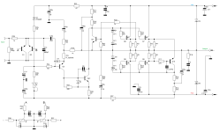
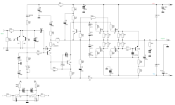
To complete the picture, now the twins as a schematic ...
I will submit measurements at the weekend. We will then see whether a tiny FET in its TO220 housing can dissipate 18W of power loss into heat to its surroundings without damage.
I will submit measurements at the weekend. We will then see whether a tiny FET in its TO220 housing can dissipate 18W of power loss into heat to its surroundings without damage.
Attachments
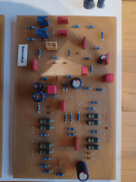
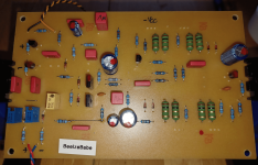
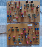
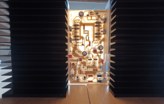
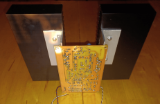
Bub lives
0,333/0,5=0,666
0,282/0,5=0,564
0,308/0,5=0,616
0,308/0,5=0,616
---------------------------------------
1.23Adc constant quiescent current.
DC offset fluctuates between -8mVdc and +32mVdc.
You don't want to touch the heat sinks for more than 3 seconds after about 1 hour - idle.
0,333/0,5=0,666
0,282/0,5=0,564
0,308/0,5=0,616
0,308/0,5=0,616
---------------------------------------
1.23Adc constant quiescent current.
DC offset fluctuates between -8mVdc and +32mVdc.
You don't want to touch the heat sinks for more than 3 seconds after about 1 hour - idle.
Attachments
- Home
- Amplifiers
- Solid State
- Beelzebub: 25 Watt for 8 Ohms