The limitation of this quick fun project is, of course, the way in which the P-channel MOS_Fet is or can be pulled along ... AN39 solves this limitation with more current, we can do this too - but then I suggest building an Aleph5 from Nelson Pass and not a "Bub or Babe".
The current (safe) limit is 20Vpp at 5Ohm.
Instabilities of other kinds still need to be recognized and eliminated, as with any other project.
#
Let's take a quick look at a SEAS woofer and sound out its series resonance ...
Oh, that's inspiring!Here's "Babe"
I'll quickly grab my pen for a beelzebabe-logo!

that's right!i see that you inverted the IPS (and VAS) polarity, wich in my opinion is a very good thing if it wasnt
for the positive side being now current limited.
That's exactly how it is, especially with MOS-FETs ...Also you know that the devil is never short of details, so i warn you that with such an implementation there s a built in
failure that could happen randomly
For the sake of Lucifer's nerves, please post the solution to this home-made problem and don't keep us in suspense.as i experimented it first hand back in the early 80s with such a design, i once spoted
a Texas Instrument implementation where they solved this issue very simply and their schematic is somewhere in this forum,
Let's delete the nostalgicHave a nice and nostalgic day
- and then I agree
kindly,
HBt.
Cool,Oh, that's inspiring!
I'll quickly grab my pen for a beelzebabe-logo!
the twins may still have a few surprises in store for us; they are irresistible in a double pack!
😉
Lucifer never lets them break out of their playpen at the same time - that could cause the normal children on the surface to suffer greatly.
Bye for now,
HBt.
Let's just let the cat out of the bag:
This two-stage circuit is a genuine class A amplifier, i.e. the current delivery capacity that has been criticized is completely normal with this concept. Simply imagine the lower P-channel MOS-FET as a constant current source. The preset current is approximately 1.2A.
Viewed as a single-ended circuit, it is now immediately clear to everyone that undesirable effects could occur if the load suddenly wants to draw an RMS current of > 850mA over a longer period of time.
However, our lower branch is modulated by the output current, i.e. actively pulled along - this is a somewhat unusual push-pull operation. Let's look at the statement
The simulations prove what we all already know, push-pull class A can deliver a maximum of twice the quiescent current as peak load current (in steady state) before the output stage, the power amplifier leaves its preset class A range. However, as 'wahab' has stated and criticized, the present topology can no longer absorb and deliver the same current in negative and positive directions without distortion. That is a fact. But it is not a flaw, as the present design does not claim to be an AB push-pull. No, Beelzebub and his twin sister Beelzebabe are real class A devils and absolutely nothing else.
So in reality there is no problem at all.
Good night and sleep well,
HBt.

This two-stage circuit is a genuine class A amplifier, i.e. the current delivery capacity that has been criticized is completely normal with this concept. Simply imagine the lower P-channel MOS-FET as a constant current source. The preset current is approximately 1.2A.
Viewed as a single-ended circuit, it is now immediately clear to everyone that undesirable effects could occur if the load suddenly wants to draw an RMS current of > 850mA over a longer period of time.
However, our lower branch is modulated by the output current, i.e. actively pulled along - this is a somewhat unusual push-pull operation. Let's look at the statement
and do the math: 10Vp/5Ohm = 2Ap !current (safe) limit is 20Vpp at 5Ohm.
The simulations prove what we all already know, push-pull class A can deliver a maximum of twice the quiescent current as peak load current (in steady state) before the output stage, the power amplifier leaves its preset class A range. However, as 'wahab' has stated and criticized, the present topology can no longer absorb and deliver the same current in negative and positive directions without distortion. That is a fact. But it is not a flaw, as the present design does not claim to be an AB push-pull. No, Beelzebub and his twin sister Beelzebabe are real class A devils and absolutely nothing else.
So in reality there is no problem at all.
Good night and sleep well,
HBt.
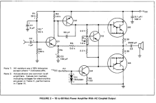
For convenience of explanations i will use the Motorola AN483B from 1974 that was ubiquitously used
by many reviews, and wich among others is the basis of the Black Devil that was published in Germany.
As you can see the IPS transistor collector is connected to the base of the VAS.
And it can happen that when powering on the amp, or during any other perturbation, the input transistor will try to command
the VAS very energically, so the collector of Q1 can sink as much current as it could through Q2 base emitter junction without
any other limitation than R5 wich is of very low value.
Hence the IPS can brutaly be broken by excess current and i once witnessed it with this very design, granted that
it use an output capacitor that will mandate a strong current to be charged at power on, hence the brutal condition
at power on but also in any other non linear condition.
The cure is of course to put a resistance in serial with Q1 colllector as well as a small capacitor in parralel of said resistance,
wich as you can see has been implemented in the Dual CV 03 amp.
Since those days one of my habits is to make sure that all paths are current limited such that there cant be any destructive
hazard that occur should it be powering on or the amp being temporarly out of its usual linear conditions like clipping for instance.
Hope it helped designing more cautiously whatever you projected as future builds.
Attachments
Last edited:
Now I've understood you, what a big misunderstanding - your basic point of criticism is as clear as mud to me and I agree with you wholeheartedly. This simple point, which is beyond any discussion, could also have led to a big bang.
thx wahab!
In this respect, I will be reviewing the simple design of the AlphaNirvanaKiller, or I will be happy to take up your suggestion for increasing operational safety (if you reveal it here?).
Apart from that, I now feel a little more sorry for the AN39-People.
😢
thx wahab!
In this respect, I will be reviewing the simple design of the AlphaNirvanaKiller, or I will be happy to take up your suggestion for increasing operational safety (if you reveal it here?).
Apart from that, I now feel a little more sorry for the AN39-People.
😢
😁😁😁Now I've understood you, what a big misunderstanding - your basic point of criticism is as clear as mud to me and I agree with you wholeheartedly. This simple point, which is beyond any discussion, could also have led to a big bang.
thx wahab!
In this respect, I will be reviewing the simple design of the AlphaNirvanaKiller, or I will be happy to take up your suggestion for increasing operational safety (if you reveal it here?).
Apart from that, I now feel a little more sorry for the AN39-People.
😢
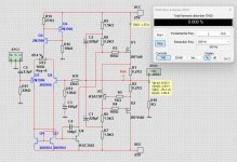
In German, we have a special word for this: “Kunststück”.Here is my clone of the Alpha Nirvana.
THD is much lower than Beelzebub - 0.00008%
In front of you, it's the "Babe or the Bub".AlphaNirvanaKiller - I'd like to see that 🙂
Imagine; if I were to dramatically increase the OLG and now counter-couple it properly, create an AB-PP modus ... 😱
A terrible thought:
0.000000000000001% THD vs. 0.05% in total!
That would be completely unproblematic and possible immediately.
You /we are welcome to take the nickname ANK as a compliment - "oder als Kampfansage" 😉.
#
So I ask,
in which direction should Beelzebub be transformed? We all know that as soon as the social police strike (including the language police, and other correction institutions ) - and Beelzebub leaves the reformatory again, his name is “Hänschen”. After his professional training as an all-purpose amplifier, we just call him "Hans".
Is that what you want?
HBt.
Dear LineUp (Linus?),
could you feed your simulator for us again and weave in wahab's curse, i.e. a “current limitation == Strombegrenzung” for the upper, active branch, so that the currents in the “Halbschwingungen” become uniform and limited -> so the N-MOS can no longer be turned up (switched) full blast.
That would be quite nice, I won't simply brush your suggestions aside, don't worry.
HBt.
⛵⛵⛵ ⛱️⛱️( The heat terror is back! )
With the gain as set by hbtaudio the necessary input voltage to reach 25W RMS is about 1.05V RMS.
With an accidental input voltage of 3.5V RMS, wich can be produced by any opamp used in a preamp, the IPS peak current
will exceed 20mA that will will get through the base emitter junction of the VAS while the IPS will see a peak power
of about 0.5W if the supply voltage is +-25V.
That s the advantage of a differential IPS wich cant drive the VAS with more than the current provided by the current
source that feed the differential.
Also, and as i already pointed it, this kind of design mandate a DC servo using an opamp
If the output DC offset is at 0V at 30°C then at 60°C it will increase to -200mV and likewise at 0°C it will be at +200mV,
hence the DC output offset variation in function of the temperature is about 6.66mV/°C...
Now if with such an IPS possible peak current and such a varying DC offset that s an OK working amp i would say that
it s a matter of personnal evaluation, but personnaly i wouldnt call this good enginering.
In fact, with this claim I would actually have to go beyond "the quick thought" and into the development lab again - maybe I will.(...) but personnaly i wouldnt call this good enginering.
HBt.
That's right!With the gain as set by hbtaudio the necessary input voltage to reach 25W RMS is about 1.05V RMS.
Total overdrive /overload; also true again!With an accidental input voltage of 3.5V RMS, wich can be produced by any opamp used in a preamp,
With this huge overload, I don't even think about any currents in the IP and VA stage.the IPS peak current
will exceed 20mA that will will get through the base emitter junction of the VAS while the IPS will see a peak power
of about 0.5W if the supply voltage is +-25V.
Again, this point is completely correct; but unfortunately Beelzebub will not receive any LTP from me.That s the advantage of a differential IPS wich cant drive the VAS with more than the current provided by the current
source that feed the differential.
This may be the case if a DC drift occurs that cannot be handled otherwise, this option is a viable solution (of a poor design).Also, and as i already pointed it, this kind of design mandate a DC servo using an opamp
I'm sorry, but I haven't switched on my thinking apparatus yet. Doesn't my intuitive approach see a DC constant current source /sink in the lower branch?If the output DC offset is at 0V at 30°C then at 60°C it will increase to -200mV and likewise at 0°C it will be at +200mV,
hence the DC output offset variation in function of the temperature is about 6.66mV/°C...
And isn't there another way to cope with the insane, propagated drift in the operating range between -75°C and +75°C of these Amp.?
This statement simply has to be measured /tested against the final structure later on.Now if with such an IPS possible peak current and such a varying DC offset that s an OK working amp i would say that
it s a matter of personnal evaluation, but personnaly i wouldnt call this good enginering.
Greetings,
HBt.
(it's not Christmas yet, so the deadline is still a long way off)
😉
In the meantime,
I am curious myself whether I will be able to solve all the points of criticism to everyone's satisfaction; whether I can do this at all?
😱
Oh I think; at the end of the day, the adult siblings will be atom bombs safe ("atombombensicher") - for sure.
evil,
Luzifer
I am curious myself whether I will be able to solve all the points of criticism to everyone's satisfaction; whether I can do this at all?
😱
Oh I think; at the end of the day, the adult siblings will be atom bombs safe ("atombombensicher") - for sure.
evil,
Luzifer
- Home
- Amplifiers
- Solid State
- Beelzebub: 25 Watt for 8 Ohms