You dont care about any suggestion.
The version is like you did from the beginning 😀
What is C_Comp for value?
The best suggestion and improvement is to make a two transistor VAS.
I have told this before.
https://www.diyaudio.com/community/threads/beelzebub-25-watt-for-8-ohms.415153/post-7737358
The version is like you did from the beginning 😀
What is C_Comp for value?
The best suggestion and improvement is to make a two transistor VAS.
I have told this before.
https://www.diyaudio.com/community/threads/beelzebub-25-watt-for-8-ohms.415153/post-7737358
That's not true at all LineUp, of course I'll be grateful for any suggestions for improvement - or do you think we've already reached the final end of the little ANK?
😉
The value? As Wahab told us, 470pF - and all of this still completely unreflected, quasi as brainstorming. Also keep in mind: my project ideas are open, open to every DIY and in every conceivable direction.
regards,
HBt.
😉
The value? As Wahab told us, 470pF - and all of this still completely unreflected, quasi as brainstorming. Also keep in mind: my project ideas are open, open to every DIY and in every conceivable direction.
regards,
HBt.

Nobody should be prevented from designing their own VAS and IPS as they wish.
However, as the father of the idea, I would be very happy to have a singleton rather than an LTP ... Ultimately, every Beelzebub bites a little differently - and that's exactly what I want, if I may say so bluntly.
#
If we could find a consensus together and tie it down by Christmas, that would be perfectly fine with me. I'm still waiting for Wahab's additions and sketches anyway.
Methink that Linus is not talking of using a LTP but to enhance the VAS this way, wich is very good idea.
Beside on second thoughts the current limitation on the negative rail is not a good idea because this will make
the amp being load impedance dependent and it wont cope with some speakers that have large impedance dips.
After some sims i would recommend a more conventional approach such that the amp can be class AB biaised
for whom is not willing to use such high idle power, after all if the THD in mid band is below -100dB there s no
way that class A would improve the sound but it will just endanger long term reliability for sure.
Attachments
Last edited:
Please explain this point in more detail and in a factual correct manner. Supporting sketches are helpful in this regard.(...) the current limitation on the negative rail is not a good idea because this will make
the amp being load impedance dependent and it wont cope with some speakers that have large impedance dips.
Said differently, the input is referenced re ground. The amp’s feedback path should be ground-referenced as well.Interesting.
You might tie the 220uF to ground rather than B+ to avoid supply noise/distortion.
PS. Just spotted post 104. Maybe already considered. 😉
Last edited:
Hello BSST,
it's dynamically (or ac-view) the same. So there must be another reason that justifies wiring up my art. But one does not have to stick to my first suggestion apodictically. Every "Bub" is a individual one.
kindly,
HBt.
it's dynamically (or ac-view) the same. So there must be another reason that justifies wiring up my art. But one does not have to stick to my first suggestion apodictically. Every "Bub" is a individual one.
kindly,
HBt.
Do you have any other suggestions?
Of course, first is to implement a DC servo using some cheap TL051 or something of the sort, because native DC offset
variation is on the order of 6mV/°C and that s just too much and would be a nightmare.
Second is to use 3 pairs of IRFs instead of 2 if you want a class A biasing as 2 is not adequate for long term reliabilty,
with 3 pairs there s much better power repartition on the heatsinks as well as lower transistors die temperature.
Third is to get rid of the bootstraps by using a separate rectifier + caps for the driver, this way supply voltage noise will be much lower, wich is important since those amps have lower PSRR than when using a LTP, with a 2 x 18V AC supply the driver will be fed
with +-25V, wich is enough to saturate the IRFs since they will have a lower supply voltage once loaded and/or class A biaised.
Please explain this point in more detail and in a factual correct manner. Supporting sketches are helpful in this regard.
The current limitation as implemented in your schematic is referenced to the negative rail Hexfets current, the transistor
limiting the current sink only the lower side Hexfets gates voltage.
For better explanations it would be necessary to reference the resistances in your schematics, R1, R2, R3 etc,
and also for the capacitors.
Last edited:
For better explanations it would be necessary to reference the resistances in your schematics, R1, R2, R3 etc,
and also for the capacitors.
Please show me the correct equipment /component labeling - "Betriebsmittelkennzeichnung".
#
With the rest you just leave me speechless.
Just one thing, I don't care how many Emitter-Follower a hobbyist wants to connect between the base electrode of the BC141 and the collector electrode of the BC177, i.e. T7 and T6.
Speechless,
HBt.
🙄
Beelzebub is not intended as an ordinary balanced (symm) MOS-FET push-pull AB Power Amplifier. That would be far too boring for me as a fun project.
Sorry, but I don't expect anything constructive here anymore. Truisms can be exchanged without my involvement.
I won't be back in this thread for the time being, but I'd be happy to return at a later date - or sooner if there is a serious interest in (building) the little amplifier called Beelzebub.
#
thx for the great logo "stv".
@hbtaudio
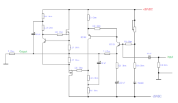
Here is the best I can do with Beelzebub parallel version.
Distortion is only THD 0.00034%

Here is the best I can do with Beelzebub parallel version.
Distortion is only THD 0.00034%
Beelzebub is not intended as an ordinary balanced (symm) MOS-FET push-pull AB Power Amplifier. That would be far too boring for me as a fun project.
Sorry, but I don't expect anything constructive here anymore. Truisms can be exchanged without my involvement.
I won't be back in this thread for the time being, but I'd be happy to return at a later date - or sooner if there is a serious interest in (building) the little amplifier called Beelzebub.
#
thx for the great logo "stv".
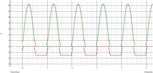
This is the current through the upper pair T1/T2 in green and the lower pair T3/T4 in red.
Output voltage is set to 14V and the load to 1R.
When T1/T2 are at full conduction there will be no voltage drop through R2/R8, so the base emitter junction of T5
will basically sense the voltage through R3/R4 and once it reach 0.65V it will conduct and sink the voltage at T3/T4
gates, wich is of no effect to limit the current through the upper pair and the upper side current wont be limited
in any way.
When that s T3/T4 that are in full conduction it s the voltage through R7/R8 that will be sensed since the voltage drop
through R3/R4 will be neligible and T5 will sink T3/T4 gates voltage once the current through R7/R8 create a 0.65V
voltage drop, and the current will be 0.65/0.5 = 1.3A per transistor, accounting for the voltage drop through R11 this will
yield about 1.5A, and since there s another Hexfet in parralel the total max current will be 3A for the negative alternance.
But why am i even explaining this, you should had spoted it better when examining the schematic of either
the AlphaNirvana or your amp project.
Attachments
Last edited:
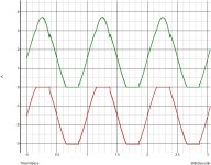
14 Ampere peak (f_signal=1kHz)Output voltage is set to 14V and the load to 1R.
speechless, as i said!
HBt.
(please don't drag me back into this thread for the time being, as soon as the heat wave has subsided and our technical sanity and reading skills have returned, I'm ready to bring the DIY project to a successful conclusion for those interested, not before).
14 Ampere peak (f_signal=1kHz)
speechless, as i said!
HBt.
(please don't drag me back into this thread for the time being, as soon as the heat wave has subsided and our technical sanity and reading skills have returned, I'm ready to bring the DIY project to a successful conclusion for those interested, not before).
That was to show that current is not limited on the positive alternance, i could had set the load at 4R and the current
limitation would still have occured on the negative alternance, you ll agree that if the amp is not 4R capable at full
voltage swing it wont sound good even in 8R.
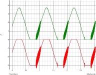
FTR here the same sim but with 18V peak and a 5R load, wich is a quite modest impendance dip for a 8R rated
speaker, and for good measure i added the same conditions without the current limiter compensation cap
in the second graph.
@lineup, 25W RMS amount to 2.5A peak output current, so 3A capability is not enough in respect
of the speakers eventual minimal impedance as well as their counter EMF, for such a power rating the amp should be capable
of 5A minimaly.
Attachments
Last edited:
Edge supplement:
I have to apologize to all friends of gender equality.
Someone must have squealed in the office, my boss is now pretty pissed off - and maybe he can light a fire under our ***, he's not called Lucifer for nothing.
Here's "Babe", the twin sister of "Bub" - whose transmutants can easily cope with any EMF of an 8-ohm woofer.
Attachments
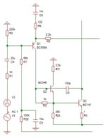
@hbtaudio, i see that you inverted the IPS (and VAS) polarity, wich in my opinion is a very good thing if it wasnt
for the positive side being now current limited.
Also you know that the devil is never short of details, so i warn you that with such an implementation there s a built in
failure that could happen randomly as i experimented it first hand back in the early 80s with such a design, i once spoted
a Texas Instrument implementation where they solved this issue very simply and their schematic is somewhere in this forum,
Dual also noticed the weird thing in one of their early amp, namely the CV3, albeit they exagerated on the value of the current
limiting resistance.
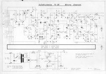
Have a nice and nostalgic day with the schematic below, the weather is very fine currently over east France and of course west Germany wich is just 17km from my location.
for the positive side being now current limited.
Also you know that the devil is never short of details, so i warn you that with such an implementation there s a built in
failure that could happen randomly as i experimented it first hand back in the early 80s with such a design, i once spoted
a Texas Instrument implementation where they solved this issue very simply and their schematic is somewhere in this forum,
Dual also noticed the weird thing in one of their early amp, namely the CV3, albeit they exagerated on the value of the current
limiting resistance.
Have a nice and nostalgic day with the schematic below, the weather is very fine currently over east France and of course west Germany wich is just 17km from my location.
Attachments
- Home
- Amplifiers
- Solid State
- Beelzebub: 25 Watt for 8 Ohms