If it does not amplify it is because you have set it up incorrectly.
What is the supply voltage, and is the 82R at the ground and the 220R to the collector of the master?
The voltage gain should then be (220+82)/82 = 3.68. If you have the resistor inverted, 82R top and 220R bottom, the gain will be (82+220)/220 = 1.37.
This might be your issue.
HD
What is the supply voltage, and is the 82R at the ground and the 220R to the collector of the master?
The voltage gain should then be (220+82)/82 = 3.68. If you have the resistor inverted, 82R top and 220R bottom, the gain will be (82+220)/220 = 1.37.
This might be your issue.
HD

@AKSA thanks, this was a quick fix.
So for the 16ohm output impedance it clips (as expected) on the negative side, before amplification has effect. (First pic)
For a 56ohm load, clipping is delayed (second pic).
Guess have to lower R1 from 330 to 220ohm?
Second, it is REALLY loud. Have to have a look at R5 and r6 values.
Third, there's a slight channel imbalance, need to understand whether is the volume pot or the master transistors' matching.
Fourth, running a sweep, it is flat but has treble rolloff, -3dB at 16kHz.
Just not able to put the picture of the sweep, did that rolling the signal generator knob 😁
At the moment, all I can say, it's that it IS LOUD
Attachments
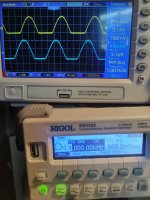

Simulation confirms that.So for the 16ohm output impedance it clips (as expected) on the negative side, before amplification has effect. (First pic)
Simulation does not confirm that. At about 80 kHz the signal begins to roll off.Fourth, running a sweep, it is flat but has treble rolloff, -3dB at 16kHz.
If R2 and R3 are swapped it begins to roll off at 20 kHz. Are R2, R3 and R4 at their right place on the board?
Last edited:
@widea, yes, it is solved, just use 5w resistors of prescribed value. I will try to bypass the big EL cap with a film resistor, and look for the treble.
By the way, have a look at this simulation: I added ammeters everywhere, to answer your question about plotting current. to show I, just click on the ammeter symbol.
By the way, have a look at this simulation: I added ammeters everywhere, to answer your question about plotting current. to show I, just click on the ammeter symbol.
Attachments
When you drive a 16R load you need to set a very high quiescent. Let us select a 4Vpp output, which undistorted gives you 125mW into 16R cans, more than enough.
4Vpp gives 2V peak, so peak current will be 2/16 = 125mA.
This means you should set a quiescent of 150mA.
Now if your supply is 24V, set the output DC point at half 24V plus 2 and we get 14V.
Assume gain of 3, and 5mA flowing through the master transistor, we will pass 155mA through the lower resistor but we need to set about 3 times less voltage at the master emitter less O.6V. This gives you 4V at the master emitter so knowing it will pass 155mA this is 25.8R, npv would be 27R.
Last we choose the upper resistor, and we know (27+X)/27 = 3, so X is 54R, npv 56R, gain will be 3.07.
There are a few issues here such as base currents but this will work well.
HD
You are welcome. As it happens, I'm designing a preamp using this gain block and I have chosen 470/220 ohm resistors giving Av of (470+220)/220= 3.13 (9.9dB), so these calculations are relevant to my work.
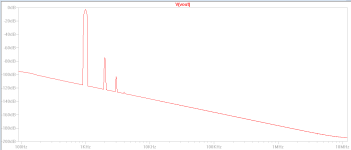
BTW, it is a VERY good preamp, improves any power amp and is almost warm, like a tube. Here is the harmonic profile at 2Vpp into 22k at 1KHz:

THD is 0.025%, highish, but H2 is dominant at -72dB and H3 at -101dB. H5, the nasty one, is at -150dB. Zout is only 15R, great for crappy cables. A CFP is a very good building block, very powerful and linear, but only in Class A. Some care is needed to ensure stability, however.
HD
BTW, it is a VERY good preamp, improves any power amp and is almost warm, like a tube. Here is the harmonic profile at 2Vpp into 22k at 1KHz:
THD is 0.025%, highish, but H2 is dominant at -72dB and H3 at -101dB. H5, the nasty one, is at -150dB. Zout is only 15R, great for crappy cables. A CFP is a very good building block, very powerful and linear, but only in Class A. Some care is needed to ensure stability, however.
HD
Attachments
Last edited:
Hugh, what do you think about early rolloff? Is it just the output cap or any other reason? Why is sim not showing it. Is your preamp showing rolloff? Have you built it and measured it? Thanks.
Ok.
Why not use headphone amp as preamp as well?
I put rca outputs on almost every headphone amp, just in case. ACP+ is great pre for instance.
Why not use headphone amp as preamp as well?
I put rca outputs on almost every headphone amp, just in case. ACP+ is great pre for instance.
You are welcome. As it happens, I'm designing a preamp using this gain block and I have chosen 470/220 ohm resistors giving Av of (470+220)/220= 3.13 (9.9dB), so these calculations are relevant to my work.
BTW, it is a VERY good preamp, improves any power amp and is almost warm, like a tube. Here is the harmonic profile at 2Vpp into 22k at 1KHz:
HD
Hey Hugh, thank you, but let me benefit from your patience for a message more... some passages were not clear to me:When you drive a 16R load you need to set a very high quiescent. Let us select a 4Vpp output, which undistorted gives you 125mW into 16R cans, more than enough.
4Vpp gives 2V peak, so peak current will be 2/16 = 125mA.
This means you should set a quiescent of 150mA.
Now if your supply is 24V, set the output DC point at half 24V plus 2 and we get 14V.
Assume gain of 3, and 5mA flowing through the master transistor, we will pass 155mA through the lower resistor but we need to set about 3 times less voltage at the master emitter less O.6V. This gives you 4V at the master emitter so knowing it will pass 155mA this is 25.8R, npv would be 27R.
Last we choose the upper resistor, and we know (27+X)/27 = 3, so X is 54R, npv 56R, gain will be 3.07.
There are a few issues here such as base currents but this will work well.
HD
>Now if your supply is 24V, set the output DC point at half 24V plus 2 and we get 14V.
For headroom?
>Assume gain of 3, and 5mA flowing through the master transistor, we will pass 155mA through the lower resistor but we need to set about 3 times less voltage at the master emitter less O.6V.
This. Ok for gain, how do you assume 5ma through the master? And the 155mA are coming out of slave collector, right? How do you know the number? Then, why 3 times less V at the master emitter?
By answering these questions, you'll let me ace the art of amp design 😀
And yes, why both me and @adason are experiencing this treble rolloff? @adason did you bypass the big EL with a film cap?
Guess you do not use preamps as headphone amp because they swing voltage, and sometimes cans require current.
Yes, i put mp cap on electrolyt, but i did not measure the difference. I am working on other projects.
Michelag, you got it other way around...any headphone amp can be pre. Not the other way as pre can not drive low impedance. Read my post again. I said i put rca on every headphone amp just in case i want to use it as pre.
Michelag, you got it other way around...any headphone amp can be pre. Not the other way as pre can not drive low impedance. Read my post again. I said i put rca on every headphone amp just in case i want to use it as pre.
Hi Mich,
Yes, for headroom. You must keep current flowing through both the master and the slave to ensure they both work together at the peak output, particularly the negative peak current. At +2V we must pump 125ma from the pair into the load and increase quiescent too, so the master has to be fully passing 5ma so both divider resistors must pull the 125ma to ground.to preserve the waveform.
5ma is a little light on because the slave base current could rise to about 2ma adding to the 5ma. On the pos half cycle the slave adds collector current to quiescent; on neg half cycle the collector current subtract from the quiescent but never turn off the master/slave.
To maintain master current constant you can replace the slave bipolar for a pmos but then you now have to design for a capacitive gate though not too serious at audio bandwidths.
The divider resistors will set the output voltage at a fixed ratio wrt the master input. This ratio is (R1+R2))R1 so since master emitter tracks 0.65V below master base at the output slave will settle under heavy feedback such that the output collector will always be input multiplied by the ratio dictated solely by R1 and R2.
I am not sure why you have treble rolloff.
It may be related to capacitance at the slave base but it might also be related to heavy capacitance in the load.
HD
Last edited:
@AKSA thanks for the explanation, need a littl time to digest.
For rolloff, the load was a resistor. have to try a non inductive resistor.
For rolloff, the load was a resistor. have to try a non inductive resistor.
yes, sorry for misinterpretationYes, i put mp cap on electrolyt, but i did not measure the difference. I am working on other projects.
Michelag, you got it other way around...any headphone amp can be pre. Not the other way as pre can not drive low impedance. Read my post again. I said i put rca on every headphone amp just in case i want to use it as pre.
I have a theory about the frequency rolloff which may be nonsense but here goes:focus more on rolloff.
Could it be the simulation program (in my case LTSpice) does not take into account the harmonics when calculating the frequency sweep? If so that explains rolloff at 80kHz in simulation and 16kHz rolloff in practice.
Then eliminating the rolloff also eliminates the harmonics. In any case I leave it as it is. The characteristics of the amplifier are probably for a great part determined by the 'harmonics profile'.
Last edited:
I can't see why LTSpice is making this mistake. My output drops from 1Vpk to 800mVpk from 10Hz to 10 megahertz, and no drop at 1MHz at all.
It doesn't make sense to me that dropping the harmonic calculations would interfere with the rolloff.
I do see a 1dB rolloff at 1MHz for 1Vpk output into 22k with a 100pF stability cap from base to collector of the slave, but absolutely nothing at 200KHz.
In all cases the harmonic profile is a typical h2 75dB H3 102dB H4 130dB H5 156dB, little change across the entire audio range but I admit this is a simulations, not measurement. I don't disagree with your measurement issues; reality is reality. The secret is to find WHY this is happening..
I would be looking to replace the slave to a fast transistor, say a 2SA1381 and a fast master say 2N5551.
HD
My idea first would be to measure with different load, to see if loading the circuit too much would caused this.
I measured with 50 ohm headphones plugged in. I can measure into 100 ohm, 500 ohm, 1k and 10k...and see if there is difference.
I measured with 50 ohm headphones plugged in. I can measure into 100 ohm, 500 ohm, 1k and 10k...and see if there is difference.
- Home
- Amplifiers
- Headphone Systems
- DIY Class A Headphone Amp suggestion