I don't need any of that 😉.
My interest goes in completely different directions - in the current case, I want to know what's going on in the industry and what the new thing is all about. The A1 may even survive 20 years in continuous operation without a single failure, but who knows for sure?. I actually assume that the people responsible at MF will also test their creation extensively, maybe as space heating - or will the customer take over from now on, in this case reliable data will not be available until 2025 at the earliest.
With my DUT, the motor potentiometer reproducibly no longer wants to be operated motor-driven after a very short operating time - just to name one effect of the internal device temperature.
But this is not going to be a drama here;
it is an A1, which may show signs of failure sooner than expected, but it is an A1, so be happy (you can be sure of regular repairs).
Joking aside!
The sound is intoxicating, the MC-RIAA-EQ is fantastic, the housing is stylish - and as long as the PE is in place and the apartment doesn't burn down... who cares?
The original circuit is known, so anyone interested can put together a Tim de Paravincini Class A Amplifier (A1) themselves, with suitable heat sinks on the right and left (as side panels of the housing) - there will be enough competent support in the forum too.
HBt.
I have to say I am not impressed with Project T/T either (new owners of MF). My wife bought me one in 2015 that had so much motor hum/noise, I returned it. Got another one a little later - hardly any better. I ended up buying a special ‘low noise upgrade’ kit from the importer Henley Designs. I managed to get it a bit quieter but it remained a dog. I eventually gave it to my son and bought a Michel. The Project was a £600 item. I bought my other son a Rega (can’t remember the model #) in 2018 for about £300. Very quiet turntable.
There is no excuse in my book for this sort of thing. If DIYers can build class A amps that last for years or even T/Ts (see Analog Source forum for example) then we should expect manufacturers to be able to do better since they by and large have more resources and experience, right? And don’t give the ‘marketing dept did it’ excuse. It’s not them.
There is no excuse in my book for this sort of thing. If DIYers can build class A amps that last for years or even T/Ts (see Analog Source forum for example) then we should expect manufacturers to be able to do better since they by and large have more resources and experience, right? And don’t give the ‘marketing dept did it’ excuse. It’s not them.
Last edited:
60 Watt per channel class A with plateau bias in a full size diyAudio Delux chassis. If I disable the plateau bias, the heatsink temp is 50C after about an hour. You need big heatsinks for class A. Luckily you can switch this to class AAB or class AB if you want.

AFAIK, it means ‘precious junk’.What doe ‘Edelschrott’ mean?
Apt description for many expensive commercial amplifiers. Doesn’t apply to any of your designs. 🙂
Blame Alps or the makers of pot ....tollerance gearboxLast repetition:
The engine potentiometer no longer likes to turn (the gearbox!) when it has become burning hot after 1.5 hours.
It seems that the temperatures reached inside the case will easily make the pot (gear) go beyond the limits imposed by its design as from Alps spec.
In other words, it simply seems yet another bad choice by the designer(s), or a consequence of it (that's the overheating). 😉

In other words, it simply seems yet another bad choice by the designer(s), or a consequence of it (that's the overheating). 😉
The quote below is from 2005 and applies to an amp from the company which became Musical Fidelity.
Seems overheating was always a problem. By the way the TVA-! was a good sounding amp in its day...when working properly.
Seems overheating was always a problem. By the way the TVA-! was a good sounding amp in its day...when working properly.
Yes - I talked to a German Hi-fi entusiast, who checked out a very erly TVA-1 to be exactly identical to the shown circuit. Find the amplifier here: Restauration TVA 1 .
Mr. Knipschild did not have any experience with his TVA-1 and burning components or tubes. On the other hand some hi-fi people had called for help with heat and fire from TVA-1 amplifiers.
Another guy in Belgium stated that some strange unexplained changes has been made to later versiones of the TVA-1.
I have heard the original without checking the values of the components. I am very sorry I did'nt. This amplifier sounded as one of the best I have ever listen to when talking about push-pull with power beyond 30 watt.
If anyone has the answer whether the stated circuit can be verified as identical to the real TVA-1 amplifier, I would like to know?
regards
Kim
TPC
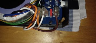
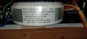
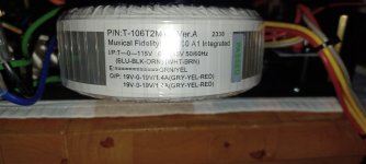
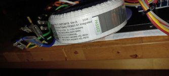
It is not possible to turn the mains transformer so that the conductors carrying the mains voltage do not touch the hot cover. The secondary side (4 times 19Vac_1.4Aac) also touches the cover with its cables.
Hopefully the PE is really in contact with the anodized cover, the heating plate.
I find this point impossible and dangerous.
Attachments
-
 20240725_174036_resized.jpg195.8 KB · Views: 83
 -
 20240725_174042_resized.jpg182 KB · Views: 82
 -
 20240725_180346_resized.jpg361.2 KB · Views: 75
 -
 20240725_180359_resized.jpg305.6 KB · Views: 87
 -
 20240725_180508_resized.jpg139.4 KB · Views: 91
 -
 20240725_180521_resized.jpg143.9 KB · Views: 87
 -
 20240725_180701_resized.jpg144.9 KB · Views: 87
PVC melts at 90 degrees I think 😀
If you own the device wouldn't it be better for the nerves to either give it back or to sell it?
If you own the device wouldn't it be better for the nerves to either give it back or to sell it?
100% agreed.to either give it back or to sell it
It may even sound really good (or very good), but it seems like an affront to intelligence.
And even subservience, in my eyes.
In my opinion, such a lot of inadequate choices cannot be "rewarded" in any way.
There's a lot of other stuff out there that sounds good.
Furthermore, with the green deal in full swing and inflated energy bills, the Class A amps don't even seem to be up to date these days. 😉
A few more comments
So there is a lot wrong here.
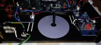
I can't remember that the old, original A1 getting as hot as the new one - the bottom of which is also at least 50°C after 2 hours of operation and the distance to the load-bearing rack surface is effectively only 10mm to 12mm - so the “Satan” heats up all around.
Somehow I hope that the responsible MF chief designer is reading this thread: a hi-fi amplifier that can no longer be touched during operation is (2024) a nogo.
- After 2 hours of operation, the lid temperature directly on the surface is 58°C and 54°C inside
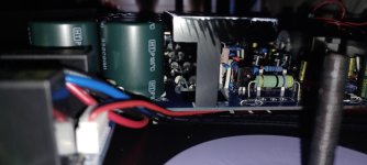
- When I look at the tiny mains transformer, tiny in terms of VA, then I know immediately that the current MF-A1 can never deliver more than 2 times 16Wrms of continuous power
- Can the MF specification of the damping factor with 150 never be correct, more than theoretically 34 are not possible with the current circuit - or is there a negative internal resistance of the two halves of the circuit(?).
So there is a lot wrong here.
I can't remember that the old, original A1 getting as hot as the new one - the bottom of which is also at least 50°C after 2 hours of operation and the distance to the load-bearing rack surface is effectively only 10mm to 12mm - so the “Satan” heats up all around.
Somehow I hope that the responsible MF chief designer is reading this thread: a hi-fi amplifier that can no longer be touched during operation is (2024) a nogo.
Side noteFurthermore, with the green deal in full swing and inflated energy bills, the Class A amps don't even seem to be up to date these days.
The A1, with its typical 0.8Adc quiescent current, is a 20Wpeak (ergo 10Wrms into 8Ohm static loads) PP class A representative.
And it doesn't have to get that hot - rails of +/-16Vdc are sufficient, as a result a modern, somewhat up-to-date A1 would only have to convert >51W power loss into heat.
As we all know, the A1 gets a little bit cooler under signal control /modulation. But not at a high room-volume, that's not enough.
Such a small class A PushPull representative should therefore not get so hot, unless the cooling element is incorrectly dimensioned, incorrectly mounted and the operating voltage is too high. Both are present in the current model!
That's another topic; but yes (regarding the Diesel file) ...Like VW killed Diesel, MF will maybe kill class A.
If anyone thinks that installing a low-noise fan is the solution, they are mistaken, because how is the laminar flow (necessary for the A1) to be generated?
Flat on the bottom sucking fresh air from below through large enough slots creating overpressure in the device and therefor blowing out hot air through ventilation slots at the back and those at the sides. Probably a non perfect way but at least it'll keep the caps and volume potentiometer OK.
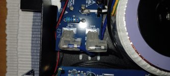
How long will the small TIP3xC survive an external housing temperature of 60°C during operation? A 1/2 hour and then they start to think about when the first of them will fail next year!
That really didn't have to happen, the alibi relays on the output side are really just ballast - or did the old ones have a switch-on/switch-off pop? No. I can't remember that.
I doubt the existence of a protective circuit - the µC and the output relay seem to be just waste.
That really didn't have to happen, the alibi relays on the output side are really just ballast - or did the old ones have a switch-on/switch-off pop? No. I can't remember that.
I doubt the existence of a protective circuit - the µC and the output relay seem to be just waste.
- Home
- Amplifiers
- Solid State
- 2023 Musical Fidelity A1