My edit in red, to clear possible misunderstanding.The tweeter andwoofermid measurements were taken at the same y hieght of 675mm and the woofer was taken at its y height of 380mm
"Almost" is not the same as "exact". Yes, 2.6 mm may make difference around the mid/tweeter crossover frequency, if it is relatively high. Also, with that method all vertical mid/high lobing is completely lost. The most precise method is to measure at the axis of each driver - it is documented in the VituixCAD help file.Using my measurment method then all the measurments have almost the same distance to baffle. Is 2.6mm really going to matter?
My edit in red, to clear possible confusion.Looking at your first post my impression is you took your driver measurements each at one axis.
You misunderstand the OP explanation about how he measured tweeter and mid, because of the OP's lapsus calami - see the first quote above.
He is not talking about that. Calm down guys, it is misunderstanding only.If you bothered to open the zip file you'd see I too all took all axis measurements from 0-90 degrees.
Last edited:
I concur.Maybe you should build the crossover like this and listen to it. Then you can start again and try a less complicated design with about half that many parts.
I don't concur. Above about 500 Hz (depending on the room) dominant is loudspeaker linearity only.You can make the response as even as you like, once you place a speaker in a room and play music, nothing of that linearity is left.
Last edited:
This is the cascaded (aka "ladder") topology, it's a good alternative that you can try if you have trouble finding your target with the standard, 3 separate filters topology. More about it by Mr. Linkwitz himself here.I like how you used one section of the high pass for both the mid and tweeter. Thats an awesome way to save some componetry.
Here's an improved version of mine, just added a tweeter trap and tweaked some other component values.
Attachments

👍 🙂Just for fun, would you include a 2200 uF cap in series with the woofer, to get rid of the small 70 Hz bump?
Be that as it may, there are a few diaphragm breakup modes that needed a bit of handling. And it's worth noting here that there are world-class loudspeaker systems that use even greater numbers of passive components.Do you know there are world class speaker that only use a few parts in the crossover?
If you're referring to the resistive losses in the inductors, then these are quite evident in the fact that they introduce some parasitic attenuation.Did no one tell you that any part in a passive crossover has a negative impact on the final sound?
However, irrespective of the room where the loudspeakers are placed in, the direct sound from the loudspeaker reaches the listener's ears before the reflected sound.You can make the response as even as you like, once you place a speaker in a room and play music, nothing of that linearity is left.
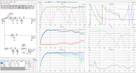
The pesky little cone-breakup resonance at 4.9kHz has been addressed in the following crossover design. It has been attenuated by another 10dB or so, putting it 60dB below the summed response. An extra inductor has been added to the midrange LPF circuit. The benefit is that it doesn't need to be tuned to the breakup resonance frequency.
What's an extra component here and there... 🙂


What's an extra component here and there... 🙂
They are LCR notches that reduce the peaks of the drivers response. The R in series with the coil reduces resonances at xo point. I agree that the crossover is complicated (and more expensive) but the drivers have multiple peaks in their responses. Anyway, I avoided components in series with the signal path and used a lower order filter: woofer and mid are LR2 acoustic (circa), while Tw is LR4.Question:
What are the purpose of these resistors just before the negative connection of you filters? I've seen others use these. Are they just for fine tuning the filter?
Mid
Tw
You should have given link to the old thread. Here it is:A few of us have been discussing this 3 way XO in another thread.
https://www.diyaudio.com/community/threads/saggy-bandpass-filter.415311/
Take this advice:
try a less complicated design with about half that many parts.
Inductors are the most expensive parts of the crossover, so their number and values should be kept at optimal (minimal 🙂 ). Capacitors for woofer filter should be bipolar electrolytic, capacitors with bigger values for mid filter also, and only the smaller values for tweeter and mid filters (and in RC notch filters) should me MKT capacitors.
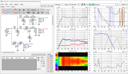
Members witwald and cabirio posted their crossover designs, both with commendable flat frequency response, albeit with high component count and higher 400-500 Hz woofer/mid crossover frequency. You wanted lower woofer/mid crossover frequency, so this is my tweaked crossover with low (245 Hz) crossover frequency between woofer and midrange and minimal number of inductors:
Last edited:
Well, mine has 3 components fewer than yours 😉 Just kidding, yours has the best off-axis response so far and I don't mind the rise in the top octave at all, I'm 57 and what happens up there is of little consequence to me, so at least on paper I'd probably pick yours over mine regardless of component count.Members witwald and cabirio posted their crossover designs, both with commendable flat frequency response, albeit with high component count
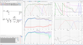
As they say, there's more than one way to skin a cat, and I think it may be useful to Bmsluite and others watching to explore different possibilities. On that note, here's another one with just 11 components. The main concern here would be the midrange driver's distortion with such shallow high-pass slope, but the ZA14W08 is actually a midwoofer with pretty good distortion figures and it could probably handle that without problems. And yes I realize the off-axis isn't great, I'm just playing here...
Well, this means war! 🙂Well, mine has 3 components fewer than yours 😉 Just kidding,...
Mine has just 8 components, of which only two inductors! 🙂
OK, now seriously: my simple crossover don't suppress well mid resonances at 4.6 kHz and 10 kHz, tweeter is not flat, but this is the cheapest possible crossover with decent sound.
I have heard of all of this yes. My first 3 way used the minimal amount of components. These drivers seem a lot more tricky than what I was using last time. The woofer and the mid both breakup at the high end.Maybe you should build the crossover like this and listen to it. Then you can start again and try a less complicated design with about half that many parts. You improve an imaginary unicorn and in that process the whole thing goes down the drain.
Do you know there are world class speaker that only use a few parts in the crossover? Did no one tell you that any part in a passive crossover has a negative impact on the final sound? And a last one: You can make the response as even as you like, once you place a speaker in a room and play music, nothing of that linearity is left.
The tweeter can't really play below 3khz.
The only simplification I see is to go 2nd order on the mid and woofer where they cross. The notch could be removed from the tweeter but I do think that needs to be there or it could end up being fatigueing to listen to
Yup, you surely did fix that low end boost with that. Wow, good call.Just for fun, would you include a 2200 uF cap in series with the woofer, to get rid of the small 70 Hz bump?
See my post here:
https://www.diyaudio.com/community/...of-this-peerless-8.415134/page-4#post-7742478
Attachments
I did modify the distance to include those 2.6mm. Nothing changed. Next time I'll take them at their exact heights. I wanted to simplify the measurement process to reduce variables. Those variables being me not getting the mic perfectly straight again.My edit in red, to clear possible misunderstanding.
"Almost" is not the same as "exact". Yes, 2.6 mm may make difference around the mid/tweeter crossover frequency, if it is relatively high. Also, with that method all vertical mid/high lobing is completely lost. The most precise method is to measure at the axis of each driver - it is documented in the VituixCAD help file.
My edit in red, to clear possible confusion.
You misunderstand the OP explanation about how he measured tweeter and mid, because of the OP's lapsus calami - see the first quote above.
He is not talking about that. Calm down guys, it is misunderstanding only.
I almost feel like it would be easier to use the 90 degree cal file for the far field measurements. Its much easier to use levels to get it straight up than it is to get it straight forward.
What is this going on with the mid crossover? That rise in XO at the highest end?Well, mine has 3 components fewer than yours 😉 Just kidding, yours has the best off-axis response so far and I don't mind the rise in the top octave at all, I'm 57 and what happens up there is of little consequence to me, so at least on paper I'd probably pick yours over mine regardless of component count.
As they say, there's more than one way to skin a cat, and I think it may be useful to Bmsluite and others watching to explore different possibilities. On that note, here's another one with just 11 components. The main concern here would be the midrange driver's distortion with such shallow high-pass slope, but the ZA14W08 is actually a midwoofer with pretty good distortion figures and it could probably handle that without problems. And yes I realize the off-axis isn't great, I'm just playing here...
View attachment 1336612
Attachments
If you experiment with the high pass 2.200uF cab, you may be able to extend the low end a little.
I usually move speaker (tweeter) around on the baffle to get a straight response, then start with the x-over.
If you need more than 18dB/oct in reality you may better go active. Cost for the passive crossover will be higher than the active version.
Also you should think about the option to digitaly equalize the whole speaker, instead of using hundreds worth of passive parts. So you might get away with a clean 12dB/oct design. Many do that without even noticing, when they have their AVR measure and correct for the room.
This looks really good. Not getting that cancelation at 300 anymore. You have a lot less inductors than I have and were able to cross lower with the mid than I could. Ours do look similar but that's because I stole that mid notch filter from you lol. I'll probably use yours since its cheaper than mine.You should have given link to the old thread. Here it is:
https://www.diyaudio.com/community/threads/saggy-bandpass-filter.415311/
Take this advice:
Inductors are the most expensive parts of the crossover, so their number and values should be kept at optimal (minimal 🙂 ). Capacitors for woofer filter should be bipolar electrolytic, capacitors with bigger values for mid filter also, and only the smaller values for tweeter and mid filters (and in RC notch filters) should me MKT capacitors.
Members witwald and cabirio posted their crossover designs, both with commendable flat frequency response, albeit with high component count and higher 400-500 Hz woofer/mid crossover frequency. You wanted lower woofer/mid crossover frequency, so this is my tweaked crossover with low (245 Hz) crossover frequency between woofer and midrange and minimal number of inductors:
View attachment 1336605
View attachment 1336606
Just for my own learning experience.... do you see any glaring issues with my crossover?
Attachments
These will be run with a WIIM amp and it has an equalizer so I can do that. I do like having a passive filter so I can move them or use them with any amp in the future if I want.If you experiment with the high pass 2.200uF cab, you may be able to extend the low end a little.
I usually move speaker (tweeter) around on the baffle to get a straight response, then start with the x-over.
If you need more than 18dB/oct in reality you may better go active. Cost for the passive crossover will be higher than the active version.
Also you should think about the option to digitaly equalize the whole speaker, instead of using hundreds worth of passive parts. So you might get away with a clean 12dB/oct design. Many do that without even noticing, when they have their AVR measure and correct for the room.
This isn't coming in right on my end. Something is offYou should have given link to the old thread. Here it is:
https://www.diyaudio.com/community/threads/saggy-bandpass-filter.415311/
Take this advice:
Inductors are the most expensive parts of the crossover, so their number and values should be kept at optimal (minimal 🙂 ). Capacitors for woofer filter should be bipolar electrolytic, capacitors with bigger values for mid filter also, and only the smaller values for tweeter and mid filters (and in RC notch filters) should me MKT capacitors.
Members witwald and cabirio posted their crossover designs, both with commendable flat frequency response, albeit with high component count and higher 400-500 Hz woofer/mid crossover frequency. You wanted lower woofer/mid crossover frequency, so this is my tweaked crossover with low (245 Hz) crossover frequency between woofer and midrange and minimal number of inductors:
View attachment 1336605
View attachment 1336606
Attachments
It doesn't work that way. You have to input value for the mid "Y", i.e. distance from tweeter to mid axis, lets say Ymid=-130mm. Your 2.6 mm is value for mid "Z". Both Y and Z influence vertical directivity (lobing).I did modify the distance to include those 2.6mm. Nothing changed.
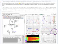
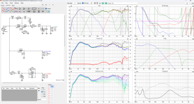
Cancelation is only in the vertical directivity (which is normal):This looks really good. Not getting that cancelation at 300 anymore.
Here is the horizontal directivity of the same crossover:
Flip the polarity of the woofer. 🙂This isn't coming in right on my end. Something is off
Last edited:
One tweak you should do with whatever xo you move forward with... Make sure all of the R, C, L values are standard values you can buy. For example if there's is a 0.68 mH inductor in VituixCAD switch between 0.65 mH and 0.70 mH since these are the readily available values. Also, look up the actual inductors you can buy and enter the actual DCR rather than what VituixCAD has estimated. Sometimes it doesn't matter, but sometimes it makes enough of a difference that you may change a component value to compensate.
- Home
- Loudspeakers
- Multi-Way
- 3 way XO help