If his still looks different, post the tab that shows your SPL measurements and impedance loaded for the drivers.
Looking at your first post my impression is you took your driver measurements each at on axis. If this is the case then this is the issue.
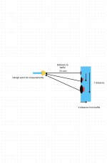
You must define your crossover design point Y. This is normally on axis with your tweeter.
Take a measurement of each driver at a fixed point Y 1 metre from the baffle.
Then use these measurements.
You must define your crossover design point Y. This is normally on axis with your tweeter.
Take a measurement of each driver at a fixed point Y 1 metre from the baffle.
Then use these measurements.

It's not that simple.This is how you do it? Just set base measument to 0 and offset the ones that were measured differently? Good to know. I am still learning
Yes, the offsets could be used to manage certain idiosyncrasies in measurement, and for listening position differences and so forth. On the other hand if you don't include Y axis differences then you can't expect vc to simulate lobing for you and so you'll have to manage power manually.
If you bothered to open the zip file you'd see I too all took all axis measurements from 0-90 degrees. I stated the Y axis measurement process I took which is straight from the VituixCad guideLooking at your first post my impression is you took your driver measurements each at on axis. If this is the case then this is the issue.
You must define your crossover design point Y. This is normally on axis with your tweeter.
Take a measurement of each driver at a fixed point Y 1 metre from the baffle.
Then use these measurements
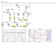
Yup, that was it! Alright, cool. We are all on the same page now!!!Got it, the cap in the woofer filter should be 100u, you have 10u
I like how you used one section of the high pass for both the mid and tweeter. Thats an awesome way to save some componetry.
Yup, that was it! Alright, cool. We are all on the same page now!!!Got it, the cap in the woofer filter should be 100u, you have 10u
I like how you used one section of the high pass for both the mid and tweeter. Thats an awesome way to save some componetry.
They look the same nowIf his still looks different, post the tab that shows your SPL measurements and impedance loaded for the drivers.
I am using an iPhone. I can’t easily open a zip. Try screen shots.If you bothered to open the zip file you'd see I too all took all axis measurements from 0-90 degrees. I stated the Y axis measurement process I took which is straight from the VituixCad guide
This is a hobby. Be kind to people offering to help. You are the one asking for help after all.
The fact is your learning. It will take you a good 12 months get your head around it until your competent.
You didn't bother to open the files and are making assumptions. Assuming people are doing things wrong is quite rude where I am from. Might be a difference of culture, this is why I am explaining my reasoning for my intonation. Many people will find that sort of thing rude. Especially when they offered all of the information, and yet the person ignored it, and assumed they were at fault.I am using an iPhone. I can’t easily open a zip. Try screen shots.
This is a hobby. Be kind to people offering to help. You are the one asking for help after all.
The fact is your learning. It will take you a good 12 months get your head around it until your competent.
Question:That's may take.
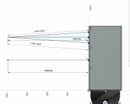
Adjust the drivers' distance. Tw is always 0,0,0 - all the others are negative (drivers should be measured at their height in cabinet, see vcad instructions).
View attachment 1336443
View attachment 1336444
What are the purpose of these resistors just before the negative connection of you filters? I've seen others use these. Are they just for fine tuning the filter?
Attachments
If this amounts to 137mm spacing on the baffle (?), this exceeds 1/4wl above 630Hz where it may make a difference.Is 2.6mm really going to matter?
I agree they're not always intuitive, especially where file operations are concerned. If you open Files/Downloads/ you should be able to click on the zip file to unpack it to a new folder.I am using an iPhone. I can’t easily open a zip.

I'd like to offer up the following modified crossover design. I have added two extra components on the woofer, in an attempt to better attenuate the woofer's breakup resonances. These were relatively high in SPL. Note that the Y-distances were determined from the drawing of the drivers on the baffle, which was presented in the earlier thread. In this circuit, both the woofer and the midrange are connected with positive polarity.


I used the following diagram to compute the Y-offsets for the midrange and woofer. Why would that be incorrect?

Just for fun, would you include a 2200 uF cap in series with the woofer, to get rid of the small 70 Hz bump?
See my post here:
https://www.diyaudio.com/community/...of-this-peerless-8.415134/page-4#post-7742478
See my post here:
https://www.diyaudio.com/community/...of-this-peerless-8.415134/page-4#post-7742478
Maybe you should build the crossover like this and listen to it. Then you can start again and try a less complicated design with about half that many parts. You improve an imaginary unicorn and in that process the whole thing goes down the drain.
Do you know there are world class speaker that only use a few parts in the crossover? Did no one tell you that any part in a passive crossover has a negative impact on the final sound? And a last one: You can make the response as even as you like, once you place a speaker in a room and play music, nothing of that linearity is left.
Do you know there are world class speaker that only use a few parts in the crossover? Did no one tell you that any part in a passive crossover has a negative impact on the final sound? And a last one: You can make the response as even as you like, once you place a speaker in a room and play music, nothing of that linearity is left.
That is for adjusting the attenuation of the resonant RLC notch filter.What are the purpose of these resistors just before the negative connection of you filters?
Last edited:
- Home
- Loudspeakers
- Multi-Way
- 3 way XO help