No, the PC being built is far from a high performance PC. It is being made from older components that I no longer use. It will be used mostly for gaming. Audio will be headphones or small powered speakers. In this case the CPU is a 7th gen Intel Core i7-7700T low power chip that I used in a portable battery powered PC on longer vacation and other road trips. As of now there is no video card, just the Intel on chip graphics. I got a list of the games she plays and built to the recommended requirements, not the minimum. Nobody in that family of 6 could tell the difference between HiFi and NoFi, they could care less, so it's on board audio, no added card.If it is a high-performance pc, you could install HQPlayer on it and explore upsampling. It deserves to be heard. Otherwise with lower performances pc you can install Daphile on a usb-pen. It is a very very good music player and can upsample as well.
For Daphile it is way more than what is needed, as I use a DELL WYSE 7010 Z90D8 AMD G-T56N 2x 1,65GHz with 4GB of ram and 2GB SSD for the OS, plus 1TB for music files. It runs with the onboard soundcard if needed, and you control it from remote through a mobile phone or whatever can surf internet.
If you think you cannot convert her to good listening, I suggest you to try it for yourself. Or, if you can have access to a higher performance PC (after the summer the new 3nm technology should lower existing processors’ prices), you can try HQPlayer.
This is not free as Daphile, but you can try it for 30 minutes sessions and then restart it again. With a 15W 13th gen i7 fanless processor I can upsample to DSD128, but I know that with 14th gen i9 it can be reached DSD1024 (with a DAC capable of reading it). It is like being in the studio while recording the album.
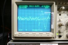
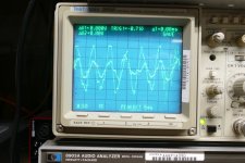
That turned out to be last night. The 6AV'5's already met the Edcors twice, many years ago and a few days ago. Tonight, the pair got to hook up with some other old friends, my Yanaha NS-10M Studio Monitors. Now I remember why I kept the old Edcors when I gave almost 500 pounds of transformers to a metal scrapper because I had two weeks to empty a house that I had lived in for 37 years and get out of Florida. After playing some musical selections from about 20 CD's ranging from guitar and a singer to full metal racket, I realized that this combo just sounds good even when it is pushed to the point where clipping is visible on the scope. The scope is connected across the speakers with both channels overlaid on top of each other. I simply kept hitting the save button randomly as the music played. The volume knob was left at full except for a few loudly mastered CD's where there was obvious distortion at full volume. For these I turned it down until there was visible but not audible distortion present. Loud bass notes didn't clip hard, but were gently rounded making them sound "fatter" as opposed to distorted. Picture 761 shows a bass guitar note at about 90 Hz. The initial transient got rounded, but not severely clipped. This is almost 30 volts peak to peak.I'll hook up some music and speakers the next time I am the only one home.
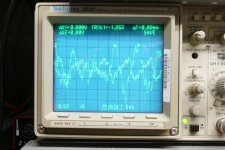
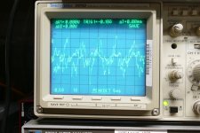
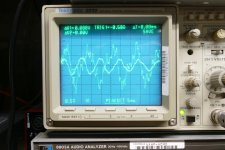
Picture #0761 shows a bass guitar hit a note of about 100 Hz, where the speakers are about 12 ohms. This light load is the reason the amp had no problem putting 28 volts peak to peak across the speaker with a slight clip on the positive peak. This is about 10 watts from an amp that can't make that much power into an 8 ohm resistor. I grabbed a few other random scope pictures of some instances where the signal is clearly clipped, but not audible, or barely audible. None of it was due to serious bass, but my speakers are over 16 ohms from 70 to 100 Hz and peak at over 20 ohms. Most of the peaks with their heads chopped off are drum hits, floor tom, tom tom or snare. Chopping their heads off is not always obvious especially if it coincides with heavy bass or guitar. There are also several instances of 25 volt peak to peak waves that are not clipped! I imagine that the results will be different with a different set of speakers.
I may try some different transformers if I can find the time before needing the test bench space for a DIY guitar amp experiment.
Attachments


Nice! Still running at 300V 65mA or have you pushed the tubes harder since the initial tests?I realized that this combo just sounds good even when it is pushed to the point where clipping is visible on the scope.
A decade or two ago I read about a commercial bass guitar amp that used a small SE amp (6BQ5 or similar) with output transformer and everything to drive a big solid state power amp through a dummy load and an attenuator. A more proper way to build a hybrid amp than just shoehorning in a 12AX7 somewhere in the circuit.Loud bass notes didn't clip hard, but were gently rounded making them sound "fatter" as opposed to distorted.
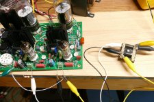
Yes, all of the testing was done on 300 volts at 65 mA or so. The tubes tend to draw a little more current after being flogged hard, since those tubes were from a box that had not been opened in at least 10 years. I just powered the bench up for another quick experiment related to my quest to "reinvent" the guitar amp. Before messing with it, I turned everything on and let it run for about 5 minutes. Both tubes idle within 3 mA of 65.
I grabbed a little Edcor transformer and used it for a phase inverter between the audio generator and the test board. I disconnected the little SE OPT's and wired a P-P OPT across both channels. I then proceeded to find max power. With a 6600 ohm load (the rating for the OPT) I could hit 40 clean watts on 400 volts with the current meter around 300 mA. I then put the 8 ohm load on the 3300 ohm tap and turned the power supply up to 450 volts. I saw 56 clean watts and cranked harder to make the analyzer read 68 watts. The current meter was pegged (goes to 300 mA) and the THD was bouncing around between 7 and 9%. Something started to smell hot, so I shut it off before I broke it.
This tells me that my DIY test guitar amp will use an UNSET board for output duties. I prefer a tube without a plate cap and the 6AV5 is the biggest octal that I have, but I have a 12 pin Compactron UNSET board in the works.
Attachments
Last edited:
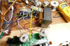
The UD board is 5 X 5 inches and the UPH board is 3.75 X 7 inches.
The UD board has an N-ch mosfet driver circuit for directly driving the grid of an output tube. The UPH board has a P-ch mosfet follower to drive the cathode of the output tube directly. Two mosfet followers are redundant so I usually leave the buffer parts off of the UD board and run a pair of wires directly from the LTP plates to the UPH board. These boards were removed from my test setup, so the wires are still in place.
The UD board has an N-ch mosfet driver circuit for directly driving the grid of an output tube. The UPH board has a P-ch mosfet follower to drive the cathode of the output tube directly. Two mosfet followers are redundant so I usually leave the buffer parts off of the UD board and run a pair of wires directly from the LTP plates to the UPH board. These boards were removed from my test setup, so the wires are still in place.
Attachments

Thanks George.
Can if using kt88's can i use the same power transformer as the SSE design? 375-0375 @175mA
Can if using kt88's can i use the same power transformer as the SSE design? 375-0375 @175mA
My amp has developed a hiss in the left channel. Kind of sounds like when you put your ear up to a seashell. It does not change with volume. I tried swapping tubes, speakers, inputs, and grounding the inputs but it remains. Any ideas what to try next?
A hiss can be caused by several things including a bad solder joint, an oxidized connector or a defective component. To determine if it's in the first or second stage, remove the driver tube and power the amp up. If the hiss is gone the driver / input stage is likely at fault.
Many years ago the first place to look would have been a tube or germanium transistor followed by a resistor. Silicon devices including a mosfet can cause hiss, but it is not as common as with germanium. Resistors are now the first place to look.
The best diagnostic tool for noisy device hunting used to be a spray can full of "freeze spray" or "circuit cool." This stuff instantly freezes a single part. If the hiss changes considerably in volume level or pitch when a component is frozen, change that part. A quick Google search reveals that this stuff, or something similar is still available. I know that the original freon based product vanished from the market in the mid 70's when people were abusing it by "huffing." If you try this, practice on some junk board as it used to take a very light touch on the spray nozzle to freeze one part at a time. I have not used this stuff since the 1970's. Never point the spray directly at a hot tube, it will shatter.
https://www.amazon.com/Tech-Spray-1.../B00012WIMK/ref=sr_1_1?crid=3HJ77VDTAKROI&dib
Thanks for the tips. Local electronics store had a can of the freeze spray. I first narrowed it down to the first stage then used the freeze spray and found it was Q101 the VP0106 FET that always seems to give me problems. I should have just guessed. I can't say how many of these I have changed out now. New one in and it is quiet again. Back to working on a case for the UNSET so I can get this one off my bench and into the house.
@Tubelab_com I remember you suggested BSS84 at the beginning. Is there something else we can try? Are the @ra7 pmosfet source follower suggested here as well?I can't say how many of these I have changed out now.
Stupid question. Could I use 2 VP0106 in parallel in Q101 ans Q201 to provide a more robust part here?
The BSS84 was used in simulations only. It just happened to be the first small signal P-ch mosfer that I found a model for. I believe that it is only available in SMD. I believe that the RA7 parts are TO-220.@Tubelab_com I remember you suggested BSS84 at the beginning. Is there something else we can try? Are the @ra7 pmosfet source follower suggested here as well?
I never tried it, but if two came from the same batch they should be close enough to work.Stupid question. Could I use 2 VP0106 in parallel in Q101 ans Q201 to provide a more robust part here?
There is mothing magical about the VP0106. When it became time to actually build the first board I stuck the closest guess at the required specs into DigiKey's search engine, hit the go button, then ordered a few pieces of several parts. At build time, I stuck a part from the first bag I grabbed at random into the board, populated the rest, and fired up the board. The board did not work on the first try, but nothing smoked and the voltages on the first stage looked good, so I looked at the part I always mess up, the diodes. Yep, the zeners across the mosfet gate in the output stage were in backwards. The board came to life, so I never looked back. That is the highly scientific method used to choose the VP0106. Despite my random poking, occasional sparks, and the usual clip lead hookup on my workbench, I have only popped one VP0106 part, and that was a hot swap of the input stage tube.
I have a perfboard experiment with an experimental circuit in it and I have popped a couple of the input mosfets. After chasing this for weeks, I found it to happen when plugging in the CD player even when everything was turned off. It turns out that the Radio Shack quality RCA cables I used make the inner connection before the outer ground shell. This forces any leakage current in the 2 wire cord line powered CD player right through the mosfet's gate. A clip lead between my CD player's metal case and the power supply ground solved the blown fet issue. All mosfets used to have an internal zener diode between gate and source. This seems to have vanished in the past 20 years. I looked up every TO92 P-ch mosfet that I have, and there is no mention of a gate protection zener in any of the data sheets.
That scenario sounds like it could be my issue as well. I have definetly blown some input FETs swapping sources. If I put an external zener between gate and source do I target the breakdown voltage of the FET?
Soldered some 56v zener diodes in place because I had them. Nothing has blown so far. Making more progress on a case, trying to stuff the 3 toroids, 2 smps, that big choke and cap plus the pcb on a 12"x12" footprint.
The gate to source breakdown voltage on the VP0106 is +/- 20 volts. Most TO-92 mosfets can handle 15 volts and a few might eat 25 or 30, so your zener should be less than 20 volts. The maximum current through the input stage is in the 10 mA range dependent on the tube being used. Any of these small mosfets should be well above 10 mA with a few volts on the gate, as the VP0106 is over 100 mA with 5 volts on the gate. Giving some room for tolerance and temperature effects, I would aim for a zener voltage of 10 to 15 volts. The old school method used two zeners in series with the arrows pointing toward each other to allow for signals on the gate that crossed the source voltage.If I put an external zener between gate and source do I target the breakdown voltage of the FET?
Thanks. I had some 12 volt zener diodes in my parts stash so went with those in series between gate and source. Turned it on and it made music so we will see if that keeps me from blowing more FETs. Kind of embarrassing seeing all the times I touched the caps with a hot soldering iron while replacing Q201.

Not much to see with the case, just a plain box so far. Under the top plate is the power toroid, choke, and SMPS heater supplies. Next is to make a top cage then cleanup and paint and some little details to try and make it look finished.

Not much to see with the case, just a plain box so far. Under the top plate is the power toroid, choke, and SMPS heater supplies. Next is to make a top cage then cleanup and paint and some little details to try and make it look finished.
- Home
- More Vendors...
- Tubelab
- UNSET Beta Board Build