Hi JohnYou´r so kind Saverio aka shadowplay62 🙂
Sadly i haven´s lear how to get the files into Vituaxcad, and my head is not what it used to be with these medications.
From time to time my head "work´s better", and that time i can be more productive 👍
My original design was ment to be "thin" like in woofer playing sideways with the side facing the listener, and mid/twe on topp.
But no doors are closed regarding woffer playing sideway´s or forward.
Woofer have 113 liters box ( before port/driver and 2 reinforcements )
So around 100 liter netto.
I downloaded you´r folder, but don´t know how to use it.
Best regards john
I'm sorry for your health condition and I hope you get better.
If you give the info regarding your speaker I can modify the project in Vcad by myself, but I need:
- Woofer Vb=100L netto (ok) / Port diameter and length?
- Midrange Vb=4L netto (ok)
- Dimensions of the front baffle for WF, Mid and TW
- Location of the drivers on the 3 baffles (Coordinates) and centre-to-centre distances of wf-mid and mid-tw.
- the response (FRD, nearfield and farfield) and the impedance (ZMA) files of the drivers.
Take care
Ciao
S.

- Woofer Vb=100L netto (ok) / Port diameter and length?
- Midrange Vb=4L netto (ok)
- Dimensions of the front baffle for WF, Mid and TW
- Location of the drivers on the 3 baffles (Coordinates) and centre-to-centre distances of wf-mid and mid-tw.
- the response (FRD, nearfield and farfield) and the impedance (ZMA) files of the drivers.
Thank you Saverio 🙂
Woofer tuned to ca 23-24 hz, round port dia 102 x 102 mm inside , 350 mm long
Midrange 4 lit netto
Frontbaffle woofer W 400 x H 600 mm, midrange H 250 x W 200 mm, tweeter 120 x 120 mm (se pic centre-to-centre )
In the Zip folder is only the Dayton 390ho impedance from manufactor specs, and the measure/FRD is from nearfield.
No port FRD files!
Mid and tweeter files is same SPL in measurement, but not the Woofer!
Best regards john
Attachments

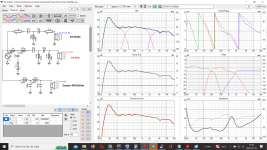
Hi Jawen, Around 50 Hz it is going to take some current but at the same time its impedance is shooting up due to the woofer resonance. Personally I think you can class it a 3 ohm loudspeaker.
Phase looks to be nicely aligned at the driver Xover frequencies, have you been practicing? 🙂 It all looks a little too clean to my eye, what is the resolution have you used ? But that is a minor point.
A question is everything taken with reference to one point, be it the mid woofer axis or the tweeter axis
As a reminder a lot of people would probably roll this off a little compared to the the nice flat response you have shown. Maybe it is worth practicing that to just to show what happens to the Xover frequencies and phase as that will move slightly as you add in some attenuation and maybe a C or L change for the mid and tweeter to obtain a gentle slope from 1kHz to 20Khz sloping down by 3dB or so.
Don´t know how i change "resolution"...I always leave things in default.what is the resolution have you used ?
Can you see that in this pic?
About the "a gentle slope from 1kHz to 20Khz" I will do that, this was just a test with the "new" SPL-traces from mic 1 meter outside.
Regards John
Attachments
Okey, then this also is like "I alway´s do", using "Var smoothing" in REW and SPL-trace from capture graf.I will double check, but i think the resolution is defined by the imported information.
The one i measured in the actual 4 liter box for SS m18 and my own SS 9300.What impedance measurements do you use?
But the Dayton 390ho has manufacturer's specs on impedance, and my measured SPL
Regards John
I think you nailed it in the simulation, the mid tweeter transition looks perfect and bass mid looks reasonable. I think the sim has done it work in that respect It is now time to build measure and listen to that Xover combination.
If the real world data matches the sim it probably would be down to tweeter resistor changes to adjust level to taste. At the same time paying attention to the 30, 40 and 60 degree responses would further refine things. Between 50 and 100Hz it will need some power if the bass impedance is as shown, You have got this far so I can assume it is not to much of an issue for the amplifier you use?
If the real world data matches the sim it probably would be down to tweeter resistor changes to adjust level to taste. At the same time paying attention to the 30, 40 and 60 degree responses would further refine things. Between 50 and 100Hz it will need some power if the bass impedance is as shown, You have got this far so I can assume it is not to much of an issue for the amplifier you use?
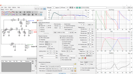
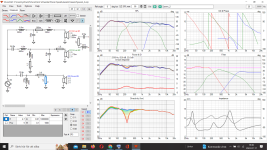
Your port (and enclosure?) tuning for the Dayton seem way off to me. Plus: the lowpass on the woofer resonates with the impedance peak(s) so you get +4dB on 45 Hz (see the electrical transfer function). This probably gets worse when you import the measured impedance. And: -15dB ref 85dB at 23Hz with this woofer? You don't need a 15" sub for that kind of performance.
How would you have done with the Dayton driver?Your port (and enclosure?) tuning for the Dayton seem way off to me. Plus: the lowpass on the woofer resonates with the impedance peak(s) so you get +4dB on 45 Hz (see the electrical transfer function). This probably gets worse when you import the measured impedance. And: -15dB ref 85dB at 23Hz with this woofer? You don't need a 15" sub for that kind of performance.
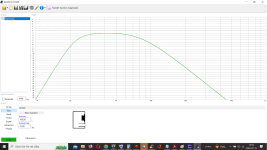
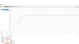
When i simulate in Winisd it look okey with 100 liter netto tuned to 23 hz (se pic)
And what is " the electrical transfer function" you talking about ?
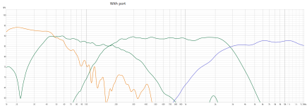
This is measured port. woofer, mid and twe ( se pic)
Do you want to see woofer measured from 2 cm
Regards john
Attachments
That is what I meant. It probably gets worse if you feed VCAD the right impedance data. You might need to correct the highest impedance peak with a tuned LCR in parallel to the woofer.
And this should be possible in a 100l enclosure. Port 120mm diameter and 525mm long. Somewhat undertuned, the room gets in heavily too, no sense in making a perfect flat alignment.
Your nearfield measurements look OK though. Why doesn't it show like that in VCad?
Okey, got you!That is what I meant.
Think its hard to "adjust" SPL from nearfield woofer response into vituaxcad because its justr "nearfield", and mid and twe is from 1 meter same level.
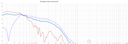
Do you mean i should "average" port and woofer response from measured, and then do "SPL-Trace" from that?
Like this?
I use a 110 mm (102 mm inside) port, and was aiming on 23 hz tuned. ( but maby it´s 24,5-25 hz tuned because my port is 32.5 cm ca)And this should be possible in a 100l enclosure. Port 120mm diameter and 525mm long. Somewhat undertuned, the room gets in heavily too, no sense in making a perfect flat alignment.
And if i simulate your suggestion in Winisd, 100 liter, 120 mm port 525 mm long iget´s 23,5 hz tuning ( so quite near my build)
Don´t know?Why doesn't it show like that in VCad?
Regards john
Attachments
Hi JohnThank you Saverio 🙂
Woofer tuned to ca 23-24 hz, round port dia 102 x 102 mm inside , 350 mm long
Midrange 4 lit netto
Frontbaffle woofer W 400 x H 600 mm, midrange H 250 x W 200 mm, tweeter 120 x 120 mm (se pic centre-to-centre )
In the Zip folder is only the Dayton 390ho impedance from manufactor specs, and the measure/FRD is from nearfield.
No port FRD files!
Mid and tweeter files is same SPL in measurement, but not the Woofer!
Best regards john
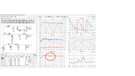
Sorry for the late answer.
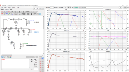
I struggled a bit to adjust the spl level of the 3 drivers. That' a summary:
- CtC distances are 175mm M-T and 370mm W-M
- Impedance minimum is 3.4 Ohm at 50Hz.
- woofer is in 100L tuned at 24Hz and I used the FR / ZR file calculated by the enclosure tool in Vcad. FRD has been generating by merging the LF and HF part in merger tool. The wf is rotated by 90° and has Z=300mm distance beacause is side-firing.
- Mid is in 4L closed box. I used your FR / ZR files
- TW I used your FR / ZR as your file
I also attached the folder with the project files.
Ciao and take care
S.
Attachments
Thank you so very much Saverio !I also attached the folder with the project files.
Ciao and take care
I envy you with such great knowledge in VitauxCAD.
Have some questions about it.
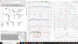
How important is the use of an LCR on the woofer in this xover ?
It has an 22 mH coil, and that size is expensive, heavy and big to fit in nice.
I play with it and try to take "away" the LCR (and still stay as close to your "curves" as I can.)
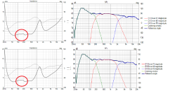
See small differences on the woofer in the " the electrical transfer function" Aka Filter in Vitauxcad, but don´t now if it´s super-important.
But the other looks "the same" (for my eye)
It was also a little differance on your posted picin "one" window.
Pic Severio is from your post # 138.
And pic Severio 1 is from the folder you did for me in that post.
Does the differance mean anything?
Edited! Is the x-point for the woofer ok at 250-ish hz ? ( was aiming on 150-180 hz originaly)
Best regards John
Attachments
Last edited:
- Home
- Loudspeakers
- Multi-Way
- 4-800 Hz wiggle i my 3 way diy