No!It was proposed to use a magic 5.1k unicorn resistor to stabilize the amplifier,
Wrong conclusion /view!however that resistor has a negative effect on THD.
Nevertheless,
well done Bernhard 🍭
Let's have a beer together (I' ll pay),
HBt.

#
Have you tested your suggestion with a jump and oscilloscoped its response? Do that!
Last edited:
The nice thing about tinkering is:
that everyone can put together their own IP-VA-Stage as they wish.
🙂
that everyone can put together their own IP-VA-Stage as they wish.
🙂
And what´s that?
I did AC analysis with the magic unicorn by the way and used the slider to see the impact of it.
I did AC analysis with the magic unicorn by the way and used the slider to see the impact of it.
The question of the meaning of the 5k1 should now be clear even to the most nagging questioner; this placeholder and reminder stands (among other things) for the final clarification of the question of stability. Without considering the Bode plot, one is unfortunately blind in this eye - or without the time domain.
5k1 -> transformed or morphed into [100Ohm+j(1/ Omega * 10nF)] - clear from the beginning.
for better illustration purpose only
with

&
without

Appendix C
Schematic with original configuration of ips.
The phase flips down exactly at 5.4k
First picture >5.4k, second picture <5.4k


And here for the extremely low value of 50 ohms to clearly show the bandwith limitations and the impact on gain.


Schematic with original configuration of ips.
The phase flips down exactly at 5.4k
First picture >5.4k, second picture <5.4k
And here for the extremely low value of 50 ohms to clearly show the bandwith limitations and the impact on gain.
None of this is a problem for the last unicorn, let's take a closer look at the first original working diagram ..!

At first glance, it is noticeable that the simulation results of MC12 differ significantly from those of my old Spice - could this be due to the models used?
Anyway, above we see the 5k1 representative with a real infinite number of ohms.

In fact, you are absolutely right, as we can see it - from 100kOhm to 100Ohm.
#
And now let's look at the case where the said fiend moves within the limits of 10kOhm to 5kOhm:

Oh dear,
from this perspective, the interjection seems to be nothing more than nitpicking (to put it kindly!).
Now let's connect a small ceramic 22pF capacitor in parallel to the 100kOhm feedback resistor and thus limit the band! I'm already very excited and looking forward to MC12's result. The tension is deadly 😱.

Checkmate!
At first glance, it is noticeable that the simulation results of MC12 differ significantly from those of my old Spice - could this be due to the models used?
Anyway, above we see the 5k1 representative with a real infinite number of ohms.
In fact, you are absolutely right, as we can see it - from 100kOhm to 100Ohm.
#
And now let's look at the case where the said fiend moves within the limits of 10kOhm to 5kOhm:
Oh dear,
from this perspective, the interjection seems to be nothing more than nitpicking (to put it kindly!).
Now let's connect a small ceramic 22pF capacitor in parallel to the 100kOhm feedback resistor and thus limit the band! I'm already very excited and looking forward to MC12's result. The tension is deadly 😱.
Checkmate!
Last edited:
Overview with Ck=22pF.
Dear Bernhard,
could you please take my advice and stop being so opinionated.
There's no point at all. But if it helps in any way, I absolutely agree with you in principle - let's look at the limiting cases of infinity and zero:
as soon as your zero can be regarded as decisive in relation to infinity, i.e. is practically zero with n ohms (always in relation to infinity), you are 100% right. Only in the applied context /task are you talking rubbish.
I'm sorry, but that's the way it is - by the way, we're definitely talking past each other.
As an aside: I don't jump back and forth between different dimensions and component selections in every simulation, but you seem to prefer to do this - which makes any comparability and illumination of your theses impossible.
Bye, bye,
HBt.
Last edited:
Does MC12 use correlate with the frequency of disputes? One might have the impression.
#
It was quite clear that the opposing party would pounce on the unicorn - and not only fall into the trap (that they have set up themselves), but also completely banish the basic analog circuit of an adder using an operational amplifier (as a synonym) from their minds.
But the bottom line is: trust your reasoning and build a test circuit, measure and determine all relevant parameters!
What's more, since MC12 often deviates significantly from PSpice in some places - whether this is important or nothing more than the parameterization and the models ... who cares ?
Last edited:
🧙♂️
@Bernhard
Basically, I think a pertinent and well-founded exchange of ideas among experts is great, but I often find it difficult to understand your motivation and commitment in this and other threads, especially since you actually have no interest in this circuit and topology (as you yourself wrote here).
In plain language, this means that you will not dare to do a test setup.
Would you like to give us, little magicians who believe in unicorns, an insight into your art, your SuperDuper - reveal the schematic of your already (through other threads, spun ...) real existing, domestic amplifier?
(Suddenly)
I feel very small right now,
HBt.
🦄
The offer stands - and now it's over with the nonsense, I'd like to get into the practice and be allowed to tinker.Let's have a beer together (I' ll pay),
HBt.
I'll get back to you with the results. In the meantime, I would be grateful if you would refrain from making assumptions or even hypotheses.
thx
🙂
In my simulation, the phase looks very different, can you post the .cir ?
I know; Bernhard, I think the origin probably lies in your *.cir back and forth.In my simulation, the phase looks very different,
I'm not sitting at the computer in question at the moment, but basically it's the cir you originally provided, I just worked with it, nothing more.can you post the .cir ?
Maybe I changed models, it's possible. While at home I use the models from Bob Cordell, Zetex, Siemens, Philips and OrCAD ... etc.
I'll be back in a week, but is it really that important? The solution is always obvious and you sit down together at the PC and use the tool of your choice.
And because, logically, we can't do that, that's where the problem lies - at least most of the time. I have experienced and observed this phenomenon countless times in my professional life.
Don't you agree? Or is narrow-mindedness and the know-it-all attitude more plausible?
That would be a shame and an absolute waste of time, but I don't want to have to assume that.
PM is possible at any time, only this time you have to unlock the channel (open a chat), I have deleted and blocked all channels open from my side.
So, if you no longer want to reject this option, it's up to you. Or publicly, with the tutorial option /thread I have activated, the ball is in your court.
Although the whistle had already been blown.
best regards,
HBt.
I have to apologize, because this request is of course also for myself (valid) - and you /we should stick to the rules as much as possible.I would be grateful if you would refrain from making assumptions or even hypotheses.
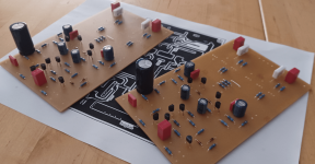
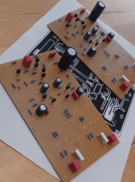
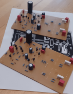
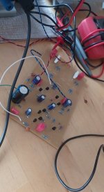
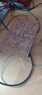
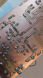
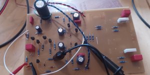
A little foretaste - quick pictures of the test panel /pcb
The drill was blunt, as you can easily see, but the snot is installed - components . Soldering will be done tomorrow and then the test will start slowly.
Experimental archiological greetings from the excavation site,
HBt.
 🍭
🍭
(let's see which BJT burns out first?, I have a suspicion!)
The drill was blunt, as you can easily see, but the snot is installed - components . Soldering will be done tomorrow and then the test will start slowly.
Experimental archiological greetings from the excavation site,
HBt.
🍭(let's see which BJT burns out first?, I have a suspicion!)
Attachments


hbtaudio - I had thought this was just a simulator exercise, but now I am impressed that you are building the amplifier.
In addition to the ripple sensitivity, I see two more problems:
* The bias current depends on the Is of six transistors and two diodes. Some means of adjustment will be needed.
* Removal of the shunt capacitors means that the amplifier is entirely dependent on transistor junction capacitances to bring down the loop gain. Capacitors may still be needed.
Be careful and good luck!
Ed
Zener diodes for static shifting of the base potential of the (inner) IPS are not necessary. The real experiment will bring the truth to light, I am quite sure of that.
regards,
HBt.
Well, the proof will be in the pudding, and seems that you collected one that is maturing since decades
in an obscure attic, for sure that it will taste something, good or bad.
Nothing beats a (good) test setup
🙄
Unfortunately, I had what felt like 1001 short circuits on the etched circuit board, which certainly cost me 4 hours of my nerves.
But to cut a long story short:
it works!
At the beginning the BC327 /337-40 of course blew, just as we all expected ... but BC546 /556B don't behave any better, you can also realize a thermal control loop, they also blow away.
Additional 10 ohm emitter resistors (E_337 -> 10, 3.3, 10 -> E_327) and a 100 ohm collector resistor each - provide a remedy. Modified in this way, the BC3x7-40 now work perfectly. The quiescent current is 11.1mAdc and remains absolutely stable.
The circuit, only the IP-VA stage (with negative feedback - loop), without the actual output stage, overdrives clean /clipping symmetrically at +/- 22.5Vp.
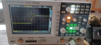
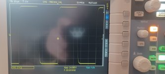
I removed all compensations during the course of the day, the complete stage does not oscillate. Nevertheless, it is not a good idea without compensation, as a 20kHz square wave clearly shows - and here the next step is already waiting.
Z-diodes in the dessert or pudding are unnecessary, I have now tried it in practice / or proven it, as you like.
I'll continue tomorrow.
HBt.
😴
🙄
Unfortunately, I had what felt like 1001 short circuits on the etched circuit board, which certainly cost me 4 hours of my nerves.
But to cut a long story short:
it works!
At the beginning the BC327 /337-40 of course blew, just as we all expected ... but BC546 /556B don't behave any better, you can also realize a thermal control loop, they also blow away.
Additional 10 ohm emitter resistors (E_337 -> 10, 3.3, 10 -> E_327) and a 100 ohm collector resistor each - provide a remedy. Modified in this way, the BC3x7-40 now work perfectly. The quiescent current is 11.1mAdc and remains absolutely stable.
The circuit, only the IP-VA stage (with negative feedback - loop), without the actual output stage, overdrives clean /clipping symmetrically at +/- 22.5Vp.
I removed all compensations during the course of the day, the complete stage does not oscillate. Nevertheless, it is not a good idea without compensation, as a 20kHz square wave clearly shows - and here the next step is already waiting.
Z-diodes in the dessert or pudding are unnecessary, I have now tried it in practice / or proven it, as you like.
I'll continue tomorrow.
HBt.
😴
Oh, I'm not sure about that yet - but the test setup will show in the end.(...) is maturing since decades
in an obscure attic, for sure that it will taste something, good or bad.
So the circuit is totally crazy, none of us would actually do it like that ... not even me. That's probably the appeal of this story.

I agree! Looking at something different you may learn something new.That's probably the appeal of this story.
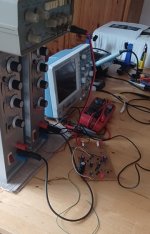
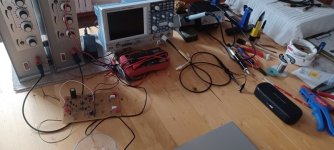
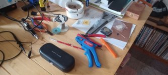
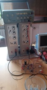
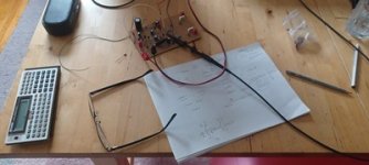
Photo album
A few chaotic pictures from the completely improvised laboratory, at 70% humidity and 28°C to 35°C air temperature in the heart of northern Germany.
A few chaotic pictures from the completely improvised laboratory, at 70% humidity and 28°C to 35°C air temperature in the heart of northern Germany.
Attachments
-
 20240630_115829_resized.jpg60.6 KB · Views: 65
 -
 20240630_115837_resized.jpg63.7 KB · Views: 79
 -
 20240630_115845_resized.jpg68.7 KB · Views: 74
 -
 20240630_120041_resized.jpg84.2 KB · Views: 67
 -
 20240630_120048_resized.jpg87.6 KB · Views: 71
 -
 20240630_120118_resized.jpg64.6 KB · Views: 73
 -
 20240630_121724_resized.jpg41.7 KB · Views: 70
 -
 20240630_121739_resized.jpg82.4 KB · Views: 68
 -
 20240630_125250_resized.jpg23.7 KB · Views: 82
 -
 20240630_125300_resized.jpg72 KB · Views: 71
 -
 20240630_142421_resized.jpg121.1 KB · Views: 82
 -
 20240630_142451_resized.jpg129 KB · Views: 73
For all those who believe that the simulator will bring them salvation without any practical or theoretical knowledge, let me make it very clear once again:
this is not the case!
1. open inputs are predestined for the most impossible oscillations, especially in inverting circuits (this is one of the reasons why the 5k1 substitute was on my notepad)
2. the layout, the cable routing and the final wiring are often responsible for the most peculiar behaviors
3. and so on.
Conclusion No.1 IPVA stage:
Stable and reliable, no more oscillation tendency, fh = f-3 is currently >200kHz, 20kHz square wave without overshoot, triangle without fault, sine wave? (THD still missing) ..!
Statically (and in steady state) everything is now paletti, dynamically quite promising ... The power amp follows: and, if necessary, an offset correction (or did the tripple B gang think I had forgotten this or that?).
HBt.
(thx to EdGr)
- Home
- Amplifiers
- Solid State
- high performance 25W PowerAmp