The Microcap oracle whispers to me: "There is no problem with the current circuit status."
Nevertheless, I don't like MC12 very much.
Nevertheless, I don't like MC12 very much.
Sorry, I forgot the daily postcard: here it is!
THD+N
10kHz, 1Wrms to 10Wrms -> smaller 0.0001% says Microcap 😉.

Slowly this amplifier can be built up with a clear conscience, it is allowed.
THD+N
10kHz, 1Wrms to 10Wrms -> smaller 0.0001% says Microcap 😉.
Slowly this amplifier can be built up with a clear conscience, it is allowed.
No. Everything is very clear.
Q5's collector just works at (...)
Yes, No, Yes, No, Yes ..!
Open loop!
But you're still right Bernhard, as I said, it's all a question of the perspective you take, and it also depends a bit on the model you use. You know, the most important thing is that the BJT models from MC12 can also reproduce what is actually on your lab bench in practice.
With the one we're playing around with here, it's completely sufficient if the simulation shows us the direction and gives us a good feeling.
The very powerful toy (in context) doesn't have to do more (than that).
Bye,
HBt.
(crafts are done on the kitchen table)
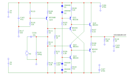
TypoThe chain consists of:
- Q6 as an impedance converter (collector circuit), at whose emitter electrode the signal is decoupled and fed to the next stage
- Q5 as the coupling stage in base circuit (whose base electrode is the actual low-impedance input of the VAS)
- followed by Q3 & Q4 working in push-pull, voltage-amplifying emitter circuit (with high-impedance output resistor)
- and low impedance decoupled via Q1 & Q2 as push-pull emitter follower.
Idlecurrent is appox (and measured) 30mA_dc+ & 35mA_dc- !
Q5 ... (whose emitter elektrode is the actual low-impedance input of the VAS)
What I actually (#461 & #462) wanted to express and ask was: if we let go of the slavish idea of the LTP differential amplifier - and accept that Q6 is an impedance converter [emitter follower] and Q5 is a coupling stage in a common-base-circuit - can't we then also select two non-identical BJTs that are possibly a little better suited to their respective tasks in order to squeeze out the last bit of THD (without increasing the OLG to gain lower thd)?
#
Does anyone feel called upon to work on this project and perhaps would like to contribute a smart PCB /Layout?
#
Does anyone feel called upon to work on this project and perhaps would like to contribute a smart PCB /Layout?
If we were to imagine that we were equal to evolution in our iterative approximate optimization process, then the following would very likely happen:
First, Q5 would slide deeper towards Q4 and eventually replace it, but then, from the point of view of the pair Q6 & Q5, it would go no further - a dead end. At this point, evolution does not yet recognize current mirrors or similar constructs, but it moves Q5 upwards again and beyond the original point, again into a dead end, the end of which, however, begins earlier than in the previous step. With this new knowledge, it takes a look at Q3 & Q4, while again moving up and down Q5 (and also the pair formed with Q6). Now a turning point occurs (a divine intervention perhaps? No!) Q4 realizes a little earlier than Q3 that he could be nothing more than a dynamic power source (this seemingly insignificant role frustrates him greatly and he decides to be stubborn from now on). His attitude leads to a transformation and Evolution decides to let him act as a static power siphon from now on. Q6 & Q5 confer and slide comfortably onto a sofa that is gently rocked by the negative provider.
This state suddenly works so well that a control loop is established and closed - adapted to his habitat and his vocation.
Q1 & Q2 have since been endowed with superpowers, while the heavyweight colossus (the Diamond Buffer) has died out.
#
This little story will take shape if we were to start simplifying and optimizing consistently at this point in time. The last result (and end!) will be Douglas Self's Blameless amp (synonymous with the familiar Lin configuration/topology).
If we are not concerned with the forms of transformation, he is still alive - Tim is alive!
Let's build it or go back to the original IP-VA stage, because this thread is about L. Stellema's article and circuit.
Another scenario could have also eliminated Q6,Q8,Q7 from the hereditary pool, up to and including the complete elimination of Q8 & Q7 including Q6 & Q5.
And it is precisely for this reason that it is not worth arguing about the nature (of the matter) here.
Perhaps North and South can now join hands without short-circuiting.

And it is precisely for this reason that it is not worth arguing about the nature (of the matter) here.
Perhaps North and South can now join hands without short-circuiting.
The L. Stellema circuit is not quite so stupid after all ...


Would you prefer @Bernhard to complete, edit and optimize the circuit and publish the THD and IM plots?
I think that would be great - a new start.
kind regards,
HBt.
( I apologize in advance, the above pamphlet is just a very quick thought, but it illustrates nicely what R19 is actually there for. )
Attachments
"Everything is very clear." [Bernhard]
R22 is the representative input resistor of the voltage follower that actually follows (the so-called diamond buffer) and should not fall below 4.3kOhm if possible, but should in any case be constant in value. I won't tell you why this is the case ...


So this frontend practically doesn't clink at all; there is some tiny little noise, but we don't hear that either.
#
The simplified circuit of the L.Stellema Original is not quite as stupid as we all wanted to make each other believe.
HBt.
R22 is the representative input resistor of the voltage follower that actually follows (the so-called diamond buffer) and should not fall below 4.3kOhm if possible, but should in any case be constant in value. I won't tell you why this is the case ...
So this frontend practically doesn't clink at all; there is some tiny little noise, but we don't hear that either.
#
The simplified circuit of the L.Stellema Original is not quite as stupid as we all wanted to make each other believe.
HBt.
Monologue - or think out loud
In the meantime, I'm feeling out the voltage follower or diamond buffer with (that funny tool) MC12!
In the worst case scenario, we end up with 15 watts of power loss for nothing - what is the strength of this configuration, independent of a headphone amplifier? Does it never switch off /the little powertransistors off?


It's a shame that I now have to play alone in the sandpit 😢.
#
R115 is to be regarded as a trimmer, variable, adjustable resistor.
In the meantime, I'm feeling out the voltage follower or diamond buffer with (that funny tool) MC12!
In the worst case scenario, we end up with 15 watts of power loss for nothing - what is the strength of this configuration, independent of a headphone amplifier? Does it never switch off /the little powertransistors off?
It's a shame that I now have to play alone in the sandpit 😢.
#
R115 is to be regarded as a trimmer, variable, adjustable resistor.
 .
.
Oh that doesn't look good around the zero point!
Thank you Nico,
I didn't know that because I never actually use MC - I'm a beginner when it comes to MC.
regards,
HBt.
So now I don't want to bore you any further with colorful pictures or even be annoying.


In any case, you can build up a buffer like this with a clear conscience, THD, THD+N, IM, ... are still missing.
Any questions?
Bye,
HBt.
In any case, you can build up a buffer like this with a clear conscience, THD, THD+N, IM, ... are still missing.
Any questions?
Bye,
HBt.
I think you /we could try out this form and dimensioning of the buffer. THD(+N) less than 0.06% in the worst case and /with 25Wrms at Rload=8Ohm - horizontally above the entire frequency range.
With R115 you /we should be able to set the output offset to zero!
With R115 you /we should be able to set the output offset to zero!
Attachments
The final stage gives me sleepless nights for several reasons, apart from the consequences of climate change.
15 watts of electrical losses for nothing - and above all, you could build a better power amplifier /buffer with the six small transistors (if we're honest).
The only attraction is the exotic status, combined with a magical wonder ..! So I'm going to tinker a bit more.
🤔
☕
15 watts of electrical losses for nothing - and above all, you could build a better power amplifier /buffer with the six small transistors (if we're honest).
The only attraction is the exotic status, combined with a magical wonder ..! So I'm going to tinker a bit more.
🤔
☕
User "Cumbb" had already mentioned it: the BD235/6 are not 100% complementary and statically they lead to a clear asymmetry. This asymmetry drives me crazy. If I set up an exotic stage and, above all, consider it outside the negative feedback loob, then it must not be worse than a simple, classic push-pull output stage.
I am attaching the latest schematic again, this time with a bootstrab and +/-25Vdc rails.
I am attaching the latest schematic again, this time with a bootstrab and +/-25Vdc rails.
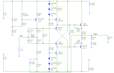
I give up trying to get more out of this circuit than is actually possible.
The thing has to go into the negative feedback loop and it has to be driven with low impedance. That's it!
So I'm sticking with my test setup for the time being - I just have to drill the heat sink accordingly. After the practical test, I'm done with this exotic device 🙁.
HBt.
- Home
- Amplifiers
- Solid State
- high performance 25W PowerAmp