Don't forget the fuse drawer!This is the one shipped with the back panel kit from the store.
https://www.mouser.com/ProductDetail/Schurter/4304.6090?qs=SkYLJkUpGh1O7%2BOWjtJ4SQ==
Whoops, this one comes with, nevermind!
Hmmm. I wonder who said that. 😉I have read ,maybe here, that sound better then Aegir 😉
I continue to use my ACA Mini Skyscraper in place of my Schiit Aegir. There really is no comparison.

In the diagram below, I have removed the connection between the center tap of the secondary and the midpoint ground of the filter bank (I don't know what else to call it). The midpoint ground is now floating, and would serve as circuit ground, but it is still connected to chassis and earth ground via a thermistor. Would there be a potential difference between this floating midpoint ground and earth ground? Is this even kosher?
(I am trying to use a transformer secondary that lacks a center tap.)

To clarify, I feel like doing so is analogous to the "floating ground" in the configuration below:

(I am trying to use a transformer secondary that lacks a center tap.)
To clarify, I feel like doing so is analogous to the "floating ground" in the configuration below:
Last edited:
(I am trying to use a transformer secondary that lacks a center tap.)
no go
you need to have properly established GND potential and this is not
you can search for Quad 606 way of doing it, but be aware of fact that being possible only for amps which load both rails in very symmetric way
F5 can qualify as that but - if you stop just for a moment and think of actual commercial worth of amp you're going to make, money spent on proper Donut is not so big deal
money spent on proper Donut is not so big deal
Exactly.
While looking up the McMaster Carr parts on the BOM I noticed a couple discrepancies in part numbers.
M3 x 10mm screws are listed as 91292A112 but are actually 8mm, the 10mm version is 91292A113
6-32 x 5/8" screws are listed as 92196A144 but are actually 1/4", the 5/8" version is 92196A150
For R3-7 the schematic and parts list mention 2W resistors, but the part numbers listed are 3W which are also what's in the kit. Is 2W ok in these spots or should they all be 3W as the part numbers/kit suggest?
The feedback resistors are fine at 2W but I would up the the 0R47 mosfet source resistors to 3W, especially if you will be running a higher bias current. Fwiw, 3W resistors are spec'd for these locations on most other FW amps
Who makes that bracket holding the toroid?
Try here: https://toroid.com/omega-bracket-vertical-mount/Who makes that bracket holding the toroid?
or contact member birdbox for a 3D printed version.
Best,
Anand.
I made an integrated out of it:
rotary switch -> DIY Frontend (gain set to 2x) -> TKD volume pot -> F5m
I’m using my own PSU:
2x 36mF -> capacitance multiplier -> F5m
-> LM317/337 -> Frontend
I did this, because I had a 2x24V/AC trafo left, that I wanted to use, so I had a couple of volts to waste.
The idle current is set to 1,29A but I’m still going to reduce it a bit. The housing is rather compact and it is getting a bit too hot for my taste.
Anyway, it sounds just sweet…
Cheers, Boris


PS: I'm still going to change the knobs, I used them because I had them. But I want bigger ones...
rotary switch -> DIY Frontend (gain set to 2x) -> TKD volume pot -> F5m
I’m using my own PSU:
2x 36mF -> capacitance multiplier -> F5m
-> LM317/337 -> Frontend
I did this, because I had a 2x24V/AC trafo left, that I wanted to use, so I had a couple of volts to waste.
The idle current is set to 1,29A but I’m still going to reduce it a bit. The housing is rather compact and it is getting a bit too hot for my taste.
Anyway, it sounds just sweet…
Cheers, Boris
PS: I'm still going to change the knobs, I used them because I had them. But I want bigger ones...
Planet IX,
Nice compact build!
What is the dimensions of the chassis and heat-sinks?
You mention you used a 2 x 24V transformer - how many VA and what is the DC voltage you got after rectification?
Nice compact build!
What is the dimensions of the chassis and heat-sinks?
You mention you used a 2 x 24V transformer - how many VA and what is the DC voltage you got after rectification?
Well, did first power up of primaries, showing just under 18v on 124v input with Antek 4218, no smoke. Next step is final wiring of PSU and boards and biasing up. A little confused on where to attach chassis ground to PS board, assuming where indicated on pic

Attachments
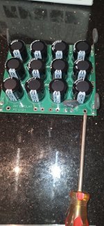
Can't see all the traces, and I've got the earlier boards, but one of the traces from the mounting holes might run to one of the thermistors. If you connect properly / securely with the mounting hardware in the kit or a metal standoff - that's your chassis GND.
Edited to add - Sheesh - yes, I just saw you had a picture attached and enlarged it. That's the one.
Edited to add - Sheesh - yes, I just saw you had a picture attached and enlarged it. That's the one.
Perfect, thx. Tomorrow I'll work on mounting the PS board and final wiring and then hopefully bias it up. Glad I went with the 4u mini-diss chassis, tight quarters still for my clumsy sausage fingers.
Planet IX,
Nice compact build!
What is the dimensions of the chassis and heat-sinks?
You mention you used a 2 x 24V transformer - how many VA and what is the DC voltage you got after rectification?
Thanks, zman01
This is the housing: https://www.ebay.de/itm/295542655383
Dimensions: 320*120*315mm
Transformer is 300VA
After the capacitance multiplier I have ~26V
Make sure they go to 11.PS: I'm still going to change the knobs, I used them because I had them. But I want bigger ones.
Nice looking build!
- Home
- Amplifiers
- Pass Labs
- F5m kit