Maybe one rail voltage pot is at the end of its travel vs what is set in the respective phono pot. My suggestion is power down first, then zero the phono pots. Measure Ohms across R12s for validating that. Power up. Start over with the voltage rail pots only for T.P. Tweak the phono pots little by little from there if necessary.

I must have gotten my pots Way out of adjustment. For a min., I could adjust TP only with voltage pot, and voltage with TP pot. I have them both at 34.2, and as close to 4.0 as I can get. I guess this is the way circuit works, and my level of electronic know how extremely limited, but it seems one or the other of these two could be controlled by a servo, leaving only one adjustment, but I have NO idea what I am talking about.
russellc
russellc
I think this is exactly what happened. I assume these are 25 turn pots, I listened for clicks but never heard them. Sometimes I have to "listen" through a paper towel roll to pick that up! Old ears...I think I have things back in range now. The way my unit is built, one board faces one way, the other the other way. maybe I turned the wrong pot. It just requires sort of see sawing back and forth. Also, I was going all extremes, setting and changing from MM to HiMC to LoMC...I was listening to Pearl 3 while I worked on this one, now to switch back out.Maybe one rail voltage pot is at the end of its travel vs what is set in the respective phono pot. My suggestion is power down first, then zero the phono pots. Measure Ohms across R12s for validating that. Power up. Start over with the voltage rail pots only for T.P. Tweak the phono pots little by little from there if necessary.
Thanks!
Russellc
I built Iron pre kit without iron.And Iron pre possibly?
My amplifier have already iron so I felt like too much.I used charcroft zfoil,Khozmo shunt attenuator with charcroft,DIY manganin wire resistor for offset.I feel much clearer than roon DSP volume but no gain.
Thanks,good to hear about Pana caps. I will try Panasonic FR someday,here FC are more around and cheaper.
Recently so many audio grade parts are disappearing here.I bought nichicon gold and KZ 100,220,470 and 1000uf for my future build.
Iron-less pre it is then. Yes, the recent go-to "audio" parts phasing out situation is a shame. Specialty arguments aside they all were known quality parts from first rate manufacturers.I built Iron pre kit without iron.
My amplifier have already iron so I felt like too much.I used charcroft zfoil,Khozmo shunt attenuator with charcroft,DIY manganin wire resistor for offset.I feel much clearer than roon DSP volume but no gain.
Thanks,good to hear about Pana caps. I will try Panasonic FR someday,here FC are more around and cheaper.
Recently so many audio grade parts are disappearing here.I bought nichicon gold and KZ 100,220,470 and 1000uf for my future build.
No worries, we do worse all the time. You are welcome.Thanks!
Russellc
Say, where are you with your VTA with the AT33ptg/2? Mine's still breaking in, but time to see.
I am curious to set up my PCB to test different capacitors for C1 and C3. Just to play around and see what difference I might hear.
Any recommended best way to set up the PCB for quickly switching between capacitors? Something like soldering alligator clips in, perhaps? Or could I get away with electric taping the connections to the board?
Any recommended best way to set up the PCB for quickly switching between capacitors? Something like soldering alligator clips in, perhaps? Or could I get away with electric taping the connections to the board?
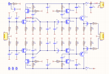
The scheme has undergone cosmetic changes to improve the parameters.
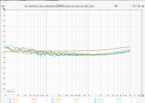
The advantage of this circuit is that it can work at different supply voltages 5V-30V
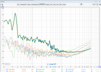
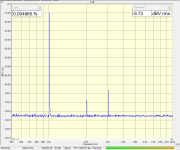
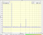
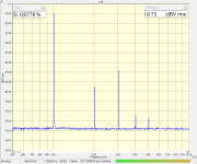
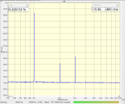
THD graphs are at different supply voltages 5V, 10V, 15V, 20V, 25V, 30V
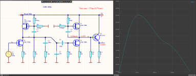
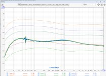
The frequency response was also measured at different supply voltages, with RIAA compensation.
For comparison, graph 6 is of the Cristl FET from the forum.
The advantage of this circuit is that it can work at different supply voltages 5V-30V
THD graphs are at different supply voltages 5V, 10V, 15V, 20V, 25V, 30V
The frequency response was also measured at different supply voltages, with RIAA compensation.
For comparison, graph 6 is of the Cristl FET from the forum.
Attachments
-
 АЧХ 8-10-15-20-30V.png142.9 KB · Views: 102
 -
 THD-5V-30V.png139.5 KB · Views: 97
 -
RIAA-JFET V1.1 (15.8.2024 г. 17-22-12).zip3.1 MB · Views: 52
-
RIAA-JFET V1.1.PDF1.8 MB · Views: 76
-
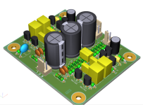
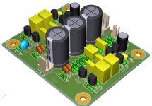 RIAA-JFET V1.1 3D.jpg103.7 KB · Views: 94
 -
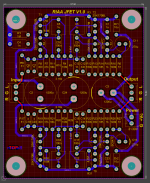
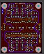 RIAA-JFET V1.1 Pcb.jpg11.1 KB · Views: 119
 -
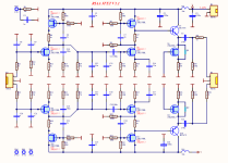 RIAA-JFET V1.1 Sch.png160.1 KB · Views: 126
 -
 THD.png223.8 KB · Views: 130
Last edited:
very nice work. What did you use to perform these measurements and what is the bump at 30Hz on the TDH graph? is it TDH+N?
What is the noise density of this circuit?
What is the noise density of this circuit?
oh soundcard I see. be aware sometimes these measurements are not accurate, but using REW and Cosmo or other card and calibrate it against calibrated analyzers will offer reliable results. I was wondering what the noise density for this phono is. what is the distortion at 500uV input ref? What is the headroom offered? Any data?
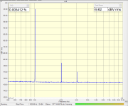
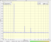
These are the distortions at 0.5Vrms and different supply voltages
And RIAA gain is 100 (40dB) for 1KHz.
And RIAA gain is 100 (40dB) for 1KHz.
Attachments
- Home
- Source & Line
- Analogue Source
- Simplistic NJFET RIAA