
If you have the 12BY7 tubes already, I wouldn't bother changing them. Not that much difference, but if you were going to sell 100s of kits, the 6197 is cheap, while 12BY7 is a bit expensive. The 6197 tubes I got came in a sealed box of 200 for some gov'mnt contract. They all seem to be matched, I was shocked. The gov'mnt contract must have been $$$$$.
Amp back and working.
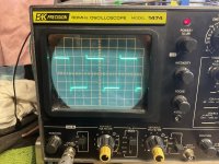
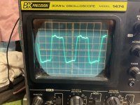
Changed C12/C15 to 10nF it improved square @ 10k. I'm done making changes.
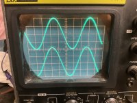
Sinewave frequency response is 20-23k -2db across the spectrum.
Thanks for all the help.
The only way I see to improve response is to possibly change out the output transformer to a Toroidy TTG EL34PP 6.6K OT.
Maybe later in the year.
Lowering the caps anywhere between 20pf to 10nf would improve the response to make it a little flatter. The drop off would be at the top end about -3db.
Changed C12/C15 to 10nF it improved square @ 10k. I'm done making changes.
Sinewave frequency response is 20-23k -2db across the spectrum.
Thanks for all the help.
The only way I see to improve response is to possibly change out the output transformer to a Toroidy TTG EL34PP 6.6K OT.
Maybe later in the year.
Lowering the caps anywhere between 20pf to 10nf would improve the response to make it a little flatter. The drop off would be at the top end about -3db.
Attachments
Final comment. it appears to more stable and cleaner.
Again. thanks for the support and help.
You all are the best.....
Again. thanks for the support and help.
You all are the best.....
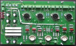
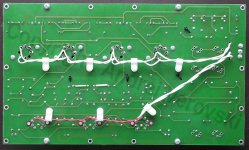
I made a mistake on my rev 4 main pcb. I mixed both the AC heater runs with the signal path. Guess what, got a great AC hum when turning on amp and running. Sorry about that. You will need to cut the heater traces from the input connection, and run new wires from point to point for all the heater runs. Don’t feel bad for me, I cleaned up the board layout and did the same mistake again. That’s part of leaning and old age.
I apologize for this oversite.
The first version Rev 4 that I posted looked good on the bench BUT had a terrible turn problem when turn on in my system.
See MP4 video below.
I'm working with a friend that more experience and better tools to help solve this problem. He does believe it can be solved.
We are working on it, but it is going to take same time. He can help me only when he has time on the weekends. His business comes first.
My friend is being nice to me, He said that I was to close to give up. I'm very fortunate to have his help and time.
I will post our results when we figure things out.
Respectfully,
Lee Mitchell
Attachments
Is this in both channels? Are the inputs shorted to avoid noise pickup?
There is oscillation after warm-up.
Suggest that you work on only one channel at a time.
There is oscillation after warm-up.
Suggest that you work on only one channel at a time.
Thanks for the reply. So far we have determined that if we apply a 5k resistor across the input, any input noise goes away.
Yes we know to do one channel at a time.
I believe that we might have oscillation after warm up. We are looking into this.
Yes we know to do one channel at a time.
I believe that we might have oscillation after warm up. We are looking into this.
There are three separate threads on this Citation project. Maybe they should be merged into one thread?
Thanks for the reply. So far we have determined that if we apply a 5k resistor across the input, any input noise goes away.
Yes we know to do one channel at a time.
I believe that we might have oscillation after warm up. We are looking into this.
How about connecting the amp to a source to terminate the inputs, does that help?
But adding a 5k resistor to ground at the input inside the amplifier does stop the noise?
Have you tried different interconnecting cables to the source, in case they are bad?
Have you tried turning off other possible noise sources, such as lights or computers,
that could couple into the audio cable?
Have you tried different interconnecting cables to the source, in case they are bad?
Have you tried turning off other possible noise sources, such as lights or computers,
that could couple into the audio cable?
I know that the cables and interface to the amp is fine, based on the amp taken out worked fine in the system. The two of us are convinced that the problems are within the tube amp
I absolutely hate that too. Can all the threads merge into just one thread? People need to stop creating threads of the same topic willy-nilly!Please do not start multiple threads on the same topic.
@smoking-amp
I build Citation II clone with 3.9K 33% UL-12% CFB, and modded its LTP, which at first sight, had quite strange balancing resistor net which I had simplified. It was a BIG mistake. Finally I balanced LTP with closely matched tubes. For whatever reason got only 50W of output before visible clipping, probably because of my LTP mods. Due to many re-solder attempts prototyping board now have too many chipped off soldering pads, is barely usable and had to be scrapped.
Did you implemented DC restorer? My LTSpice sims show it does have positive effect - lower THD at high level/low frequency.
Smoking-amp, can you please share your mods?Hegemen himself said the UL loops were a mistake. And the local plate to grid loops on the 12BY7 drivers just waste gain from the outer loops. So there are 4 loops you can take out.
I have accumulated some parts to build a "modified" Citation II. All the plate to grid loops are coming out. I suppose a triode output stage would be the natural alternative to UL, but instead,
I build Citation II clone with 3.9K 33% UL-12% CFB, and modded its LTP, which at first sight, had quite strange balancing resistor net which I had simplified. It was a BIG mistake. Finally I balanced LTP with closely matched tubes. For whatever reason got only 50W of output before visible clipping, probably because of my LTP mods. Due to many re-solder attempts prototyping board now have too many chipped off soldering pads, is barely usable and had to be scrapped.
Did you implemented DC restorer? My LTSpice sims show it does have positive effect - lower THD at high level/low frequency.
- Home
- Amplifiers
- Tubes / Valves
- Citation II - 2023