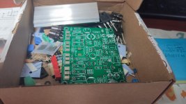
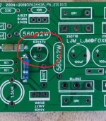
I need an electrical schematic too, for this version. I see some modification on pcb, instead of LM334 i found two diodes, and instead of coil 22uH i found a resistor with 0 ohm value. All of those where covered with some epoxi.
https://i.postimg.cc/ZRsxQbbS/Se510cb3c6afe4f628b63ef59f1816bcct.webp
https://i.postimg.cc/502mpYMg/photo-2024-03-02-12-29-49.jpg
https://i.postimg.cc/rpJJSG7z/photo-2024-03-02-12-29-49-2.jpg
https://i.postimg.cc/ZRsxQbbS/Se510cb3c6afe4f628b63ef59f1816bcct.webp
https://i.postimg.cc/502mpYMg/photo-2024-03-02-12-29-49.jpg
https://i.postimg.cc/rpJJSG7z/photo-2024-03-02-12-29-49-2.jpg

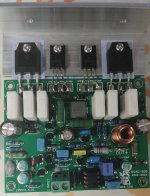
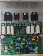
Nice, You've been able to remove this kind of soft dough on the "LM334 and J503" properly......
👍
👍
Yes, i heat up with some hot air and then i carefully remove the epoxy.
The epoxy starts to break down when you heat up.
The epoxy starts to break down when you heat up.
Hello, I decided to buy a set of 606. I had collected a couple of 707 before, everything was fine. But 606 doesn't work as it should. The constant output voltage in one channel is 31 mV, in the other 190 mV. The frequency response is overwhelmed from 8 kHz. Huge noise and distortion.
Attachments
This is wrong. Where can I find the actual schematic for which this board is made? The board doesn't work and without a real circuit it's hard to fix it!Это Quad 707, версия LJM не модифицирована, за исключением других используемых компонентов.
Attachments
Repaired the board. The Chinese seller put faulty operational amplifiers and 1.0 mF capacitors with a high leakage current in the kit. After replacing these elements, the constant output voltage was maintained within 6 mV.
Don't you wonder if that is common in all kits? A few bad parts can ruin something nice. Not sure how you found the problems?
I always check all the details before installation. But I decided to double-check with a multimeter that all resistors were installed correctly. And the 2M2 resistor showed a resistance of about 500K. The resistance leakage turned out to be due to the 1.0 uF capacitor. Perhaps I haven't found everything yet. I don't think all kits are like this. I bought two sets of QUAD 707 from different sellers and everything was fine. And the operational amplifier looked different from the ones I bought earlier and there was corrosion on the legs. I just replaced it with the Lm301 that I had.Don't you wonder if that is common in all kits? A few bad parts can ruin something nice. Not sure how you found the problems?
Attachments
I don't think the 1UF capacitor is damaged. Because it is a CBB capacitor.This is wrong. Where can I find the actual schematic for which this board is made? The board doesn't work and without a real circuit it's hard to fix it!
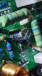
I think it's possible that the 25V33UF capacitor is damaged. It is an OSCON capacitor produced by Samwha capacitors in South Korea
But I once discovered a 25V33UF samwha OSCON capacitor with a short circuit. Replacing it with a 25V22 or 35V47UF ordinary electrolytic capacitor can solve the problem.
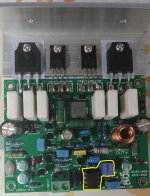
A diode is a constant current diode. Also known as a steady current diode. Place the circuit in a fixed current state of 1.5MA.
Can replace 2SJ503 and LM334. Diodes can also be omitted. The use of IC has the same effect as JFET.
So it cannot be replaced. Be careful to protect. So I applied glue to avoid collision damage.
Fourthly, I believe that the operational amplifier TL271 cannot be damaged. It is a genuine product produced by Texas Instruments.
It is recommended not to replace with LM301 or other operational amplifiers. Although operational amplifiers are universal. But the effect will vary.
Due to network reasons, I rarely access DIYAUDIO. If you have any questions, please email me: ljm_ljm@foxmail.com
Hello!
I bought two quad 707 power stages
DC current 55.5 v- 0v -55.5 volts
Can this still be used or is it too much for him?
If it's a lot, what can I do to reduce it below 50 volts...?
Maybe the recommended 45 volts?
I bought two quad 707 power stages
DC current 55.5 v- 0v -55.5 volts
Can this still be used or is it too much for him?
If it's a lot, what can I do to reduce it below 50 volts...?
Maybe the recommended 45 volts?
There is no problem with +-50V DC. Please note that KTA1049 has a high temperature. Silicone grease is required.
The output transistor 2SD718 does not generate much heat.
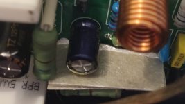
Hi! I soldered 2 pairs of QUAD 707 and a pair of QUAD 606 and on all copies the voltage boost capacitor gets very hot. The temperature on the fingers feels about 50-60 degrees Celsius. I insulated this capacitor with a thick piece of mica to eliminate their heating from the 560 ohm resistors, but this did not help. This is not useful for electrolytic capacitors. It is unknown how long they will work with such heating.
Attachments

Please check the voltage rating of the capacitor and the correct orientation.
Naturally, everything is correct there with the location and parameters of all 6 capacitors on all six boards. I used supply voltage from different DC sources, transformer and pulse from +- 2x36V to 2x45V. Not difference. Perhaps no one paid attention to this heat on their boards.
Last edited:
There is no reason for the bootstrap capacitor to run hot unless it is under-rated or reverse-polarized. It should be 47uF 63V with the polarity as shown in the 707 schematic.
I’m answering for the second time, maybe my English is so bad. The capacitors are strictly in accordance with the QUAD707 circuit and has the nominal value is 47.0 μF 63V. I put a thick piece of mica for thermal insulation from the 560 ohm resistorThere is no reason for the bootstrap capacitor to run hot unless it is under-rated or reverse-polarized. It should be 47uF 63V with the polarity as shown in the 707 schematic.
Attachments
Last edited:
Hello!
The dc output voltage I measured earlier was + - 55.5 volts at 230 ac voltage.
Now I measured 235 volts and the dc side was 58 volts.
I'm worried that the amplifier might not be able to withstand such a high voltage.
A friend of mine lives a few meters away from a high-voltage transformer, and he usually measures up to 250 volts.
At 250 volts, the dc side would be more than 60 volts.
Can the amplifier panel be modified for this reason or should I look for another transformer?
Sorry if it's not completely understandable, my English is not very good...
When does the capacitor gets hot? With or without signal?Hi! I soldered 2 pairs of QUAD 707 and a pair of QUAD 606 and on all copies the voltage boost capacitor gets very hot. ...
Whith signal, the bootstrap capacitor is subject to ripple current and has to be choosen according to this ripple current. So no fancy boutique part here but sturdy smoothing cap type (choose a low ESR type whit a ripple current twice the DC current trough the 560 ohm resistors over the entire audio frequency range).
If it gets hot whitout signal, then it is either heated by the resistors, reverse biased or underrated voltage-vise. Or the amp is oscillating, which puts you in the first case.
- Home
- Amplifiers
- Solid State
- QUAD 707 - DIY