Please explain what your alleged slew-rate graphs are intended to exhibit. The Quad 405's slew rate is already adequate to 1MHz.
BTW your claimed 30% difference at 20Hz evaporates to 3% in terms of perceived loudness. This does not inspire confidence.
BTW your claimed 30% difference at 20Hz evaporates to 3% in terms of perceived loudness. This does not inspire confidence.
@ljm_ljm I apreciate your works 😉 and I am agree with you 😉 I don't want to pollute your topic. I never listen a Quad amplifier but I know they exists.
I didn't like SMPS power supply too, until this Hypex which is very good. Hypex seems to produce among the best class D amplifier in the World.
Note The amplifier Benchmark AHB2 is a curious beast, expensive, stratospheric low noise and performance, with a SMPS working at 500kHz. I have changed opinion about SMPS, its depends on the design.
Hi,I don't know how to make holes myself. That screw hole is too troublesome.
I will have the chassis manufacturer drill the screw holes.
If you want to drill the holes yourself, I recommend using a pointed punch tool and hammer (and wear safety glasses). A drill press could greatly improve the hole precision, as it keeps the drill bit aligned with the metal being cut.
Interesting you were not impressed with the 405. I didn't like the 33/303 combo at all. The 909 was nice.

SR..SR......Please explain what your alleged slew-rate graphs are intended to exhibit. The Quad 405's slew rate is already adequate to 1MHz.
BTW your claimed 30% difference at 20Hz evaporates to 3% in terms of perceived loudness. This does not inspire confidence.
Do you know what SR means.
Attachments
Yes. If used for industrial SMPS. It usually works at 100K.@ljm_ljm I apreciate your works 😉 and I am agree with you 😉 I don't want to pollute your topic. I never listen a Quad amplifier but I know they exists.
I didn't like SMPS power supply too, until this Hypex which is very good. Hypex seems to produce among the best class D amplifier in the World.
Note The amplifier Benchmark AHB2 is a curious beast, expensive, stratospheric low noise and performance, with a SMPS working at 500kHz. I have changed opinion about SMPS, its depends on the design.
Use LC for attenuation. So we may hear high-frequency interference sound in the speaker.
If it uses 500K PWM. I think this is the correct plan.
Because using the same LC. Its PWM will decrease by a very low amplitude. Although it still exists.
Use SMPS power amplifier. You can touch the 10R 1W resistor with your hand.
It is a ZOBEL network. It can detect the output signal. Is there any high frequency beyond the audio range.
If it heats up. Indicates that your power supply has PWM interference.
If there is no fever, it is normal.
Attachments
I am very familiar with QUAD405.Hi,
If you want to drill the holes yourself, I recommend using a pointed punch tool and hammer (and wear safety glasses). A drill press could greatly improve the hole precision, as it keeps the drill bit aligned with the metal being cut.
Interesting you were not impressed with the 405. I didn't like the 33/303 combo at all. The 909 was nice.
Because I may have sold 80% of the QUAD405 for DIY.
It is also a good amplifier. I have been making QUAD405 since 2006
From my research, I found that QUAD606707909 is basically the same.
And QUAD405 and 405-2 are basically the same.
Take QUAD707 as a reference. It has a significant difference compared to QUAD405.
It is more like a modern mainstream amplifier. And QUAD405 is more like an old-fashioned amplifier.
Although their structures are very similar. But performance indicators. There is a significant difference from the effect. It can be said that it sounds completely different.
Attachments
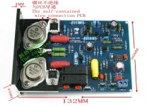
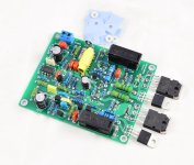
Due to the large installation width of QUAD707.
I have redesigned QUAD606. It is almost identical to QUAD707.
I have redesigned QUAD606. It is almost identical to QUAD707.
Attachments
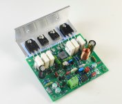

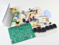
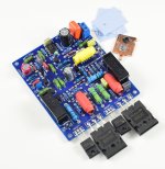
Looks great! Looking forward to buy it at Aliexpress / Aiyima Technology store. Let us know when it will be available to buy.I have redesigned QUAD606
There is sales. It's very cheap. All components have excellent quality.Looks great! Looking forward to buy it at Aliexpress / Aiyima Technology store. Let us know when it will be available to buy.
They are all genuine parts.
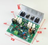
The price of mono is approximately $7. You need to assemble it yourself.
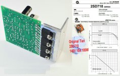
2SD718 is very good. And it is guaranteed to be genuine.LJM, are you alright?
Can the 2SC718 be replaced by the 2SC5200 without damage?
There are many counterfeit goods in China for 2SC 5200. 80% is fake. It doesn't make much sense.
Of course. If you happen to have 2SC5200. It can also be replaced.
In fact. The output transistor is not important. It does not affect performance. Driving transistors is more important, which is KTA1049. I use KEC original products. It is very important. Cannot be replaced.
Thanks LJM.2SD718 is very good. And it is guaranteed to be genuine.
There are many counterfeit goods in China for 2SC 5200. 80% is fake. It doesn't make much sense.
Of course. If you happen to have 2SC5200. It can also be replaced.
In fact. The output transistor is not important. It does not affect performance. Driving transistors is more important, which is KTA1049. I use KEC original products. It is very important. Cannot be replaced.
So I'll keep the 2SD718.
Looking forward to the arrival of this amp.
Can I use a +50/-50VDC supply normally?
There is no problem with +-50V DC. Please note that KTA1049 has a high fever. Silicone grease is required.Thanks LJM.
So I'll keep the 2SD718.
Looking forward to the arrival of this amp.
Can I use a +50/-50VDC supply normally?
The output transistor 2SD718 does not generate much heat.
LJM, I hope you are well.
Is 63V symmetrical too much for this amplifier?
Even using large heat sinks
Is 63V symmetrical too much for this amplifier?
Even using large heat sinks
LJM, I hope you are well.There is no problem with +-50V DC. Please note that KTA1049 has a high fever. Silicone grease is required.
The output transistor 2SD718 does not generate much heat.
Is 63V symmetrical too much for this amplifier?
Even using large heat sinks
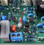
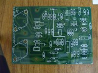
Optimizing the Quad 707 bridge
If you purchased the 707 kit, you can optimize the compensation Quad (Wheatstone/Maxwell) bridge by replacing the two presoldered parallel 1k resistors, with two resistors of 1k2 (1%) for the optimal balance.
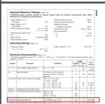
Clarades: you cannot not apply a symmetrical 63V, see the KA1049 specs.
If you purchased the 707 kit, you can optimize the compensation Quad (Wheatstone/Maxwell) bridge by replacing the two presoldered parallel 1k resistors, with two resistors of 1k2 (1%) for the optimal balance.
Clarades: you cannot not apply a symmetrical 63V, see the KA1049 specs.
Thank you for your attention.
I will build in a dual mono configuration with a symmetrical 46VDC power supply for each Quad. So it will stay within the safety margin.
Out of curiosity, what would be the total voltage limit of this amplifier?
In the original electrical scheme we have something close to +/- 54VDC.
Thanks again.
I will build in a dual mono configuration with a symmetrical 46VDC power supply for each Quad. So it will stay within the safety margin.
Out of curiosity, what would be the total voltage limit of this amplifier?
In the original electrical scheme we have something close to +/- 54VDC.
Thanks again.
- Home
- Amplifiers
- Solid State
- QUAD 707 - DIY