Hi LJM
i like the sound of the quad405 after modifications.
i would like buy your 707, but is it possible set the sensivity to 1v ou 1.5v?
if yes can you say me how and with resistors value.
thanks in advance, and thanks for your work.
bastien.
i like the sound of the quad405 after modifications.
i would like buy your 707, but is it possible set the sensivity to 1v ou 1.5v?
if yes can you say me how and with resistors value.
thanks in advance, and thanks for your work.
bastien.
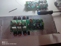
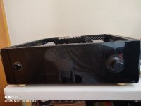
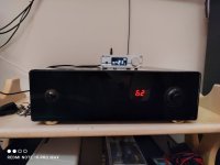
My version of the Quad 707.
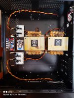
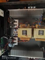
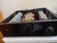
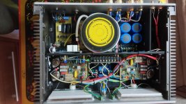
Dual mono configuration using identical Yamaha transformers and original Elna capacitors in the power supply. Transformer donors were removed from the Yamaha receivers.
I mounted the heatsink fins facing the inside of the case to act as a shield against EMI that could be emitted by the transformers.
This amplifier has been playing music above half volume since 10 am and the heating is normal, so I will keep the heatsinks arranged.
I installed a digital volume control, easily found on Aliexpress.
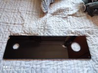
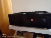
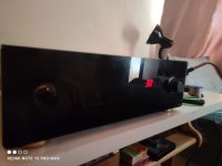
The panel is 8mm thick tempered glass, where a very dark film for automotive glass has been applied, so when the amplifier is turned off, what you see is just a block of glass with two black aluminum knobs.
When turned on, the volume indicator display appears discreetly without disturbing you in a dark room.
The sound... I'm amazed, it was exactly what I was looking for throughout my DIY audio saga, an impactful sound, but without being rude.
Its sound resembles the sound of good vintage amplifiers and receivers, but with better definition of mids and highs.
The bass is powerful and the amplifier has an absurd cone control.
Congratulations LJM, with your 707 I can say that it is the best amplifier I have.
Happy New Year to everybody.
Dual mono configuration using identical Yamaha transformers and original Elna capacitors in the power supply. Transformer donors were removed from the Yamaha receivers.
I mounted the heatsink fins facing the inside of the case to act as a shield against EMI that could be emitted by the transformers.
This amplifier has been playing music above half volume since 10 am and the heating is normal, so I will keep the heatsinks arranged.
I installed a digital volume control, easily found on Aliexpress.
The panel is 8mm thick tempered glass, where a very dark film for automotive glass has been applied, so when the amplifier is turned off, what you see is just a block of glass with two black aluminum knobs.
When turned on, the volume indicator display appears discreetly without disturbing you in a dark room.
The sound... I'm amazed, it was exactly what I was looking for throughout my DIY audio saga, an impactful sound, but without being rude.
Its sound resembles the sound of good vintage amplifiers and receivers, but with better definition of mids and highs.
The bass is powerful and the amplifier has an absurd cone control.
Congratulations LJM, with your 707 I can say that it is the best amplifier I have.
Happy New Year to everybody.
Attachments
-
 IMG_20230927_140816.jpg322.5 KB · Views: 434
 -
 IMG_20230927_144629.jpg359.8 KB · Views: 451
 -
 IMG_20230927_144641.jpg421.9 KB · Views: 453
 -
 IMG_20231104_143840.jpg439.1 KB · Views: 448
 -
 IMG_20231228_113001.jpg427.8 KB · Views: 441
 -
 IMG_20231115_124650.jpg591 KB · Views: 396
 -
 IMG_20231228_141446.jpg247.7 KB · Views: 370
 -
 IMG_20231228_141452.jpg313.5 KB · Views: 367
 -
 IMG_20231228_141457.jpg335.9 KB · Views: 365
 -
 IMG_20231228_141631.jpg201.1 KB · Views: 353
 -
 IMG_20231228_141646.jpg182.1 KB · Views: 326
 -
 IMG_20231228_141652.png632.8 KB · Views: 332
 -
 1703879528778.jpg230.9 KB · Views: 394

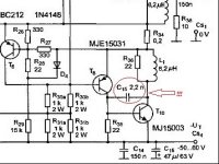
Hello, this is a great job. I have already assembled several QUAD 405 amplifiers based on Keith Cnook modifications. Now I want to try QUAD707. Could you post the electrical circuit diagram of your amplifier modification? Thank you!
Attachments


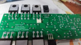
the BC556 and 2N5551 transistors are not connected well to each other, because the emitter of the BC556 must be connected to the base of the 22N5551, whereas in the PCB design this is not the case.........Due to the large installation width of QUAD707.
I have redesigned QUAD606. It is almost identical to QUAD707.
i transistor BC556 e 2N5551 non sono collegati bene tra loro, perché l'emettitore del BC556 deve essere collegato alla base del 22N5551, mentre nel PCB non è cosìSembra fantastico! Non vedo l'ora di acquistarlo nel negozio Aliexpress / Aiyima Technology. Fateci sapere quando sarà disponibile per l'acquisto.
i transistor BC556 e 2N5551 non sono collegati bene tra loro, perché l'emettitore del BC556 deve essere collegato alla base del 22N5551, mentre nel PCB non è così

Please post in English.
the BC556 and 2N5551 transistors are not connected well to each other, because the BC556 emitter must be connected to the base of the 22N5551, whereas in the PCB this is not the case

I think the polarities of a 2sc2240 are fine instead of the 2n5551, I'll try when I get the cards, and I'll mount the 20 microhenry inductor
apparently, as someone has already talked about it in the past, the 2n5551s have different polarities compared to the ncc5551s is ok quad606 pcb
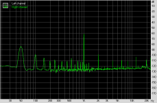
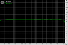
I bought a set of quad 707 on Aliexpress. I'll post measurements of the technical characteristics after assembly.
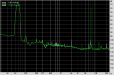
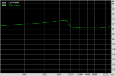
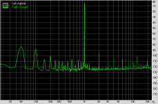
Here is one channel quad 707! The supply voltage is bipolar 2x38 volts. Load 8 ohms. D/C output voltage 0.6V. Maximum power 60W before sine wave limitation. What do you say friends? I think the noise level should be much less.
Attachments
-
 photo_2024-01-31_12-05-40 (3).jpg182.7 KB · Views: 348
 -
 photo_2024-01-31_12-05-40.jpg153.9 KB · Views: 254
 -
 photo_2024-01-31_12-05-38.jpg111.2 KB · Views: 225
 -
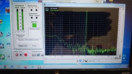 photo_2024-01-31_12-05-38 (2).jpg167.3 KB · Views: 231
 -
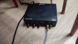 photo_2024-01-31_12-05-39.jpg153 KB · Views: 235
 -
 dynamics.png7.3 KB · Views: 222
 -
 fr.png3.5 KB · Views: 211
 -
 imd.png6.9 KB · Views: 192
 -
 imdswept.png3.8 KB · Views: 187
 -
 noise.png7.3 KB · Views: 207
 -
 thd.png7.6 KB · Views: 256
 -
 707.jpg69.4 KB · Views: 307
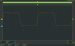
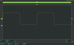
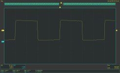
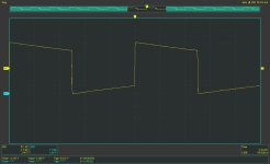
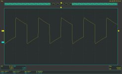
Here's another square signal! From 50Hz to 100kHz.
Attachments
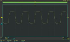
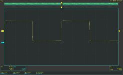
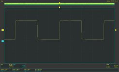

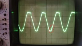
I connected a 1000pF capacitor between the collector and the base of the lower output transistor, as in QUAD 405. The oscillogram was corrected, the self-excitation of the amplifier stopped!
Attachments
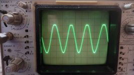
This is a good point and the right decision.I connected a 1000pF capacitor between the collector and the base of the lower output transistor, as in QUAD 405.
Attachments
- Home
- Amplifiers
- Solid State
- QUAD 707 - DIY