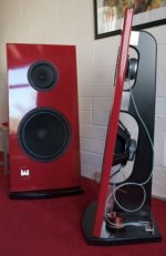
@Leob I'm wondering if our distortion problems on the 30HESF are not caused by the coil former collapsing... if you zoom in a bit then it looks like that former might be a bit tired?Here's a close-up of the XT32-4 on the left, with the ubiquitous DAEX30HESF-4 for comparison:

Certainly looks a bit wrinkly to me...@Leob I'm wondering if our distortion problems on the 30HESF are not caused by the coil former collapsing... if you zoom in a bit then it looks like that former might be a bit tired?
no I don't think so but you could look into it just to make sure.Don't stereo cartridges read both horizontal and vertical in a 45degree alignment?
Glad that my curiosity has been helpful. The shape of the panel seems so counter intuitive to me for preventing the corners from flapping. Hard to shift gears and get into a different mindset with dml panels. So are you suggesting that more shallow curves on the panel side might be an improvement? thanks.Thanks @moray james for resurrecting some of the old posts.
"That Paper," by Ben Zenker et al, mentions voice coil break-up as being one of the causes of poor upper frequency response.
View attachment 1288794
The VC buckles under the mechanical stress of driving the (panel-plus-air) load at higher frequencies.
If we look at the Xcite drivers more closely, it's good to see that Ben has applied exactly this paper's solution to the XT32 drivers. The solution being the reinforcement of the VC, and which explains why they get a much better HF response especially when loaded with a higher density, heavier panel.
Here's a close-up of the XT32-4 on the left, with the ubiquitous DAEX30HESF-4 for comparison:
View attachment 1288798
The XT32-4 not only has the VC bonded to the spider a lot higher up and closer to the load face, but also has a nice, thick layer of epoxy all around, supporting it even further.
And the proof of the pudding...
View attachment 1288799
Highlighted red is the XT32-4, the DAEX30HESF is the light blue curve. The drivers were mounted at the standard 2-5ths/3-5ths positions.
The panel is a 40 x 50cm canvas frame, with a resin-hardened Nidaplast insert which is shaped to minimise corners flapping around too much. Like this:
View attachment 1288800
Because of the weight of the very stiff Nidaplast/resin combination, which is quite heavy, bonded to the stretched canvas surface, I get a VERY nice bass response! But it's a bit ragged down there and I might be tempted to either change to a taller aspect ratio, or pay some attention to the steepness of those arched cut-outs.
Hi Andre,The panel is a 40 x 50cm canvas frame, with a resin-hardened Nidaplast insert which is shaped to minimise corners flapping around too much. Like this:
Cool idea . 👍 Similar to Steve's canvas suspended ply panels
For the corners, have you tried inserting a radiused fillet in each to 'soften' them in stress/deflection terms??. It may allow the peaks in the Nidaplast insert to be reduced
Eucy

The corners of the canvas are limited in movement by the wooden frame itself. The shaped Nidaplast's 'fingers' extend into those corners, and are glued down quite solidly. Therefore, the tips of those fingers are fixed points that don't move at all. The gradually-increasing width of those fingers means that the panel is progressively damped closer to the tips. If the panel was not mounted to the canvas, and was not mounted by its corners, then the corners would have to be rounded off to control the undamped vibration.Glad that my curiosity has been helpful. The shape of the panel seems so counter intuitive to me for preventing the corners from flapping. Hard to shift gears and get into a different mindset with dml panels. So are you suggesting that more shallow curves on the panel side might be an improvement? thanks.
I used the canvas specifically as a high compliance "surround" to allow the panel to move freely, but yet not in an uncontrolled manner, in order to improve the bass response. In my Twinwall gig panels I had the panels clamped down all around, and this reduces the bass response significantly.Hi Andre,
Cool idea . 👍 Similar to Steve's canvas suspended ply panels
For the corners, have you tried inserting a radiused fillet in each to 'soften' them in stress/deflection terms??. It may allow the peaks in the Nidaplast insert to be reduced
Eucy
I'll do further testing and try to optimize the whole canvas setup to mimic a high-Qts open-baffle driver—a driver such as the Eminence Alpha-15a. If I can get the cheap Alpha-15a driver to deliver an almost flat response down to 45Hz in a completely open-baffle configuration, then there's no reason I can't get a panel, with a larger surface area, to do the same or better.
The only thing that I'd have to address is the inevitable suck-out at the first break-up mode.
do you mean that rather than the corners going to a long point that they wold have a small semicircular notch at the end which would result in two smaller points at each corner? I hope this makes sense.Hi Andre,
Cool idea . 👍 Similar to Steve's canvas suspended ply panels
For the corners, have you tried inserting a radiused fillet in each to 'soften' them in stress/deflection terms??. It may allow the peaks in the Nidaplast insert to be reduced
Eucy
re the alpha- 15 was that slot loaded (front or bottom)? thanks.I used the canvas specifically as a high compliance "surround" to allow the panel to move freely, but yet not in an uncontrolled manner, in order to improve the bass response. In my Twinwall gig panels I had the panels clamped down all around, and this reduces the bass response significantly.
I'll do further testing and try to optimize the whole canvas setup to mimic a high-Qts open-baffle driver—a driver such as the Eminence Alpha-15a. If I can get the cheap Alpha-15a driver to deliver an almost flat response down to 45Hz in a completely open-baffle configuration, then there's no reason I can't get a panel, with a larger surface area, to do the same or better.
The only thing that I'd have to address is the inevitable suck-out at the first break-up mode.
i think you knew i would ask which panel is that? thank you.https://drive.google.com/file/d/1kdh1yNhkZY9F1waNljSoVIBvRwwy2Uj0/view?usp=sharing&authuser=0
This is a link to Leobs panels doing a sound check 😄
I am very sorry for the very poor low quality of the recording 🤮
But I think it gives you the idea of the sort of sound eps can give.
Try and imagine this in a small venue 🫣
Eps is the most efficient material I know of so far, and can play realistic machine gun fire in my room ,at ear shattering levels.
This is with my 10watt exciters.
A random picture of one of my panels.
Why do I need EQ if I roll off the frequency at say 100hz ?
I suppose I could take a few db off above 10k if I felt it needed it.
Steve.
That sounds nice, I love Bob James. thanks.It sounds like we're barking up similar trees!
I've been using my panels for live gigs. I'm just a one-man with acoustic guit, bass guit, voice and backing trax. I use three drivers per panel—one 30HESF-4 and two 25FHE's all wired series/parallel. Plenty loud enough if I roll off the bass at about 150Hz and use a separate sub.
Yes, I found that as well, and it's a massive advantage in some of the venues I work. Instead of using multiple cabs to cover the audience, I can use only two panels and get ultra-wide coverage without having to worry about dead spots, lobing, combing, directionality, sweet-spots or any of the other problems inherent in using different drivers, with different response curves, pointing in different directions.
Nice thing too is that I don't need floor monitors because even if I'm positioned "behind" the panels, I can still hear the mix perfectly clearly.
I actually found less reverb problems, possibly due to the diffuse nature of the wave-front?
I use the panels with subs on stage. Of course, the 150Hz cross-over point takes care of the possible lack in that region if aligned correctly.
Also, when using cone speakers I almost always put a low-Q notch into the 200Hz region anyway to compensate for almost every indoor venue's upper-bass modes, and to get rid of the mud in the sound, and to bring out the vocals more clearly.
In the attached clip, I've rolled off the bass end for testing purposes while assembling the panels. .
You can see the perforated back panels standing around, waiting to be assembled into the frames. As you have, I've also mounted the drivers directly into the back for support purposes.
View attachment 1266251
The Nidaplast fingers are stuck into the corners horizontally between the wood and the canvas, and then glued solid. The tips of those fingers can be sharp or truncated or scalloped, it doesn't matter what the shape is because they're fixed points encased in glue.do you mean that rather than the corners going to a long point that they wold have a small semicircular notch at the end which would result in two smaller points at each corner? I hope this makes sense.
Just a plain open baffle. No slots. No loading. No wings. A single 20mm thick plank just wide enough to accommodate the driver and high enough to screw a tweeter into.re the alpha- 15 was that slot loaded (front or bottom)? thanks.
Quote "To me driver placement does not seem essential to what modes can be excited. " please explain what you mean? the impact of the motor in whatever location you place it will have varying effects on the diaphragm which will vary with frequency as well as level and there will also be panel related effects which will also be variable. For every different driver location you have a different situation then adding multiple motors and it only becomes more and more complex. The motor and the panel combination is a veritable can of worms of back and forth interactions. It makes me dizzy to think about it.To me driver placement does not seem essential to what modes can be excited. The plate has its mode structure, and depending on where you place the exciters they will work more or less for or against the existing modes, and the effect is far from absolute. What surprised me was that moving around the clamping seemed to have more effect than moving around the exciter. I think that typically the plate suspension will be a lot more rigid compared to the exciter which is really only adding mass making the mode a little bit harder to excite.
And I don't think the exciter has to be at the peak of a node to excite it to the maximum excursion. It is similar to how a driver interacts with the air mass in a sub, where at some frequencies small movement still results in a lot of air movement at the port or mouth. The exciter ends up in a position where it basically gets leverage against the modes inherent in the plate.
Moray .
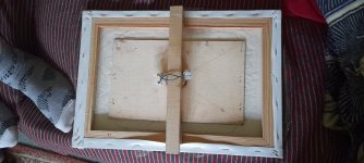
I just took a few pictures of some old test panels, which were lying around.
The first on the left is the back of my cascamite canvas panel with the enlarged crate ply attached.
I would have tried a larger crate ply but that was all I had.
Minimising the amount of loose canvas to stop flapping or buzzing.
I do not remember any problems with the corners?
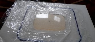
The second picture is the front of this panel.
I had forgotten that I cut away the canvas from the panel to minimise the damping on the panel 🤗
Which was handy for the cling film , giving a mm or so separation .
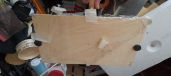
3rd and 4th are of a crate ply with weights for this panel only.
Two points were used for mounting, plus some film for testing.
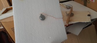
The last is an old 5watt (I think) exciter on a low density EPS panel.
Steve.
I just took a few pictures of some old test panels, which were lying around.
The first on the left is the back of my cascamite canvas panel with the enlarged crate ply attached.
I would have tried a larger crate ply but that was all I had.
Minimising the amount of loose canvas to stop flapping or buzzing.
I do not remember any problems with the corners?
The second picture is the front of this panel.
I had forgotten that I cut away the canvas from the panel to minimise the damping on the panel 🤗
Which was handy for the cling film , giving a mm or so separation .
3rd and 4th are of a crate ply with weights for this panel only.
Two points were used for mounting, plus some film for testing.
The last is an old 5watt (I think) exciter on a low density EPS panel.
Steve.
Attachments

Thanks I will have a look at these and give them some thought. I appreciate you posting them. do you remember how many card panels you made? I am still having a bit of a hard time adjusting to panel size and level with DML panels. one of your card panels was 6x9 inches so how much larger would a panel need to be to play appreciably louder than that one would (I guess I should ask hoow loud that one willl play with subs) assuming that the bass roll off of the larger panel was adjusted to match the smaller panel? I cannot seem to understand how small or how large I need to build. I would be happy with the ability to play average level of 95 db and peak capability of over 100 db db. I don't often play this loud but some music just calls for those levels to feel right. Is this expecting too much from a small panel? thanks Steve.
with a drill press you could lose a lot of panel weight and see what that sounds like?Moray.
The crate ply is a very flexible panel , in one direction only.
Although the rigidly in the other direction is not very rigid.
I presume this material is similar , maybe, to flexible ply ?
As I have said before, I like flexible light panels.
The sound of this panel is similar to my eps panels, but is still a little too heavy for that ultimate sound that I like.
And thanks for liking my recordings, much appreciated 👍
Steve.
Here's a pic of an open baffle Alpha15a similar to the one I built with my partner a while ago.re the alpha- 15 was that slot loaded (front or bottom)? thanks.
Attachments
I'm not saying it has no effect, but that it doesn't seem essential. I cannot claim to understand exactly how and why, I just found that moving around the exciters does have an effect on the FR, but it is much more marginal than I would have expected. The properties of the plate and how it is suspended seems to pretty much decide the FR, and then you can do minor adjustments with for example exciter placement and weights.Quote "To me driver placement does not seem essential to what modes can be excited. " please explain what you mean? the impact of the motor in whatever location you place it will have varying effects on the diaphragm which will vary with frequency as well as level and there will also be panel related effects which will also be variable. For every different driver location you have a different situation then adding multiple motors and it only becomes more and more complex. The motor and the panel combination is a veritable can of worms of back and forth interactions. It makes me dizzy to think about it.
The driver will vibrate the whole panel and make sound regardless of being placed on a node or an antinode. I think this is why the placement of the exciter is more forgiving than the suspension of the panel.
If it made sound only from the resonance modes of the panel, the frequency response would look really bad.
If it made sound only from the resonance modes of the panel, the frequency response would look really bad.
It's true that DML panels make sounds at all driven frequencies, not just at the resonances. But they do tend to make sound more readily at resonances, and especially at some particular resonances that are especially good at radiating sound. And not only can they radiate really well (i.e. loudly) at those frequencies, they can also ring (i.e. resonate long after the originating signal is gone) at those frequencies. And for those reasons, sometimes the frequency response and spectrograms of DML's truly do look really bad! This is especially true at low frequencies, where modal density (resonances/octave) is low.The driver will vibrate the whole panel and make sound regardless of being placed on a node or an antinode. I think this is why the placement of the exciter is more forgiving than the suspension of the panel.
If it made sound only from the resonance modes of the panel, the frequency response would look really bad.
In my experience, there are basically two ways deal with this basic issue. One is simply to use a DML only above the frequency at which all the lumpiness and ringing disappears. Depending on your choices, this could be in the range of 300 to 1000 Hz.
The second way is to use good design principles to (a) distribute the natural frequencies regularly based on the aspect ratio, suspension points and elastic moduli of the panel (b) judiciously position the exciter to equally excite those resonances, and (c) add sufficient damping to spread/widen the resonance frequencies from individual sharp spikes, to broad humps that overlap. With this method, it's easily possible to obtain good frequency response down to 100 Hz and perhaps lower.
Eric
- Home
- Loudspeakers
- Full Range
- A Study of DMLs as a Full Range Speaker