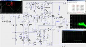
Hi, Maxlorenz! Please try this scheme .
It is necessary to solder two diodes each.
It is necessary to solder two diodes each.
Attachments
Last edited:
Thanks, dear Printnik for the many advices.
Dear Hans Pollak adviced us before of this overload protection circuit and it seems to be better with a small R in series. It should improve stability in trade for headroom...I suppose using a lower V source (like a 33V zener) accounting for the reduced V supply expected at prolonged musical peaks would be a responsible move...I confess I have not tried it yet because I do not torture my systems at all: I use moderate/high volume levels.
Maybe someone will try your version which has nice THD. Maybe later he/she would be inclined to test the LTMD/CFP input version of it, which degrades THD a little but should bring the taste of the experimental amp. Mine are sounding cristalline and clean as good tube amps but with the precision and control of modern solid state amps.
I thank you all guys for your persistent support and stimulation to make this a nice experience with even some working and nice sounding amps.
I laugh at myself at this most improbable exploit for an eternal beginner.
Cheers,
M.
PS: tomorrow will be a great day...
Dear Printnik,
Perhaps we misunderstood each other: the anti-parallel diodes I was talking about were D4-D7 // to C3 by your diagram...I do not get the usefulness of them...
Cheers
M.
Perhaps we misunderstood each other: the anti-parallel diodes I was talking about were D4-D7 // to C3 by your diagram...I do not get the usefulness of them...
Cheers
M.
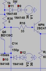
Hi Maxlorenz !. These diodes - D4, D7 reduce the gain of the differential cascade during overload, and this reduces ripples in subsequent cascades. They also reduce voltage drops on the collectors of the differential cascade. But in this scheme, this effect is not very pronounced.
Great. Thank you. I'll implement them.Hi Maxlorenz !. These diodes - D4, D7 reduce the gain of the differential cascade during overload, and this reduces ripples in subsequent cascades. They also reduce voltage drops on the collectors of the differential cascade. But in this scheme, this effect is not very pronounced.
I will try to figure it out.
Cheers,
M.
Hi dear,
I am doing great, just not very inclined to DIY, only to listen to music and "prepare" for the incoming energies of Feb/March.
The Amnesis amp with input added inductors are sounding as a good match between the best of tubes and transistors.
Please share your conclusions to evaluate if they can be implemented here...after the ****
Please remember my offer of PCBs...mailing is a nightmare these days, though...
Many thanks for the interest and stimulus,
Best wishes and Love,
M.
Hi Maxlorenz,
I was very impressed with your developments!
Can I have your personal email?
With respect
Trifonovaudio
trifonov.audio@gmail.com
I was very impressed with your developments!
Can I have your personal email?
With respect
Trifonovaudio
trifonov.audio@gmail.com
Hi Step,
Sorry for the late reply...
I answered though email and DIYaudio mailing system or whatever the name...
Cheers to All.
M.
Sorry for the late reply...
I answered though email and DIYaudio mailing system or whatever the name...
Cheers to All.
M.
Hi guys,
Some updates...
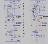
First: I've been studying the Hawksford FB VAS (read as trying to understand how it works) as improvement for the nice AMPSLABS C200 SIKLAI (which usually improves THD by one order of magnitude) when it ocurred to me that I could introduce positive FB to it from the output, comparable to the Bootstrap for the Bootstapped VAS AMNESIS....THD improves in some but not all versions but the curves...the curves look all nice....😀
Then, I made a fast drawing for revisiting the AMNESIS with CCS Hawksford FB VAS: good for experimenting....you know I like positive FB....
Some updates...
First: I've been studying the Hawksford FB VAS (read as trying to understand how it works) as improvement for the nice AMPSLABS C200 SIKLAI (which usually improves THD by one order of magnitude) when it ocurred to me that I could introduce positive FB to it from the output, comparable to the Bootstrap for the Bootstapped VAS AMNESIS....THD improves in some but not all versions but the curves...the curves look all nice....😀
Then, I made a fast drawing for revisiting the AMNESIS with CCS Hawksford FB VAS: good for experimenting....you know I like positive FB....
Attachments
Second:
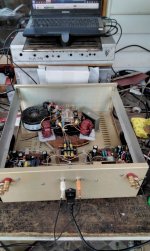
AMNESIS gets a Baluned PS!
I will not insist on this wonderful discovery of mine. I simply will show you what I am doing, for now on.
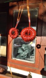
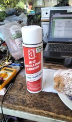
I bought some big ferrites from China (1Kh to 300Kh) and a Pro Varnish good for 150° Celsius and 4700V or so, in order that moderators DO NOT close this thread or eliminate this posts...no I'M joking: in order to reduce or eliminate any risks. L = 47mH; interwinding C = 970pF. 57 turns for each rail.
The effect of this Baluned (especial CLC) Power Supply is Yuge!
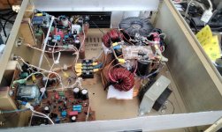
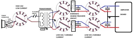
The biggest effects are in bass- midbass output, dynamic contrasts and overall power perception, it makes you want to reduce the volume setting from the TVCs.....As I wrote elsewhere, the "Bifilar Current Reisert Balun" probably gets its effect by balancing currents bewteen (power Rail versus Ground; differential mode) and Inside the wires, reducing skin-effect and group delay, appart the HF effect that is probably more easy to understand, with reduced noise floor and increased detail...but I am not an expert....by "treating" also the ground currents, it cancels the main criticism of ECdesings "Chrage-Transfer" supply.
The example shown lacks the balun for the secondary windings for the TX, which may be not needed...I need experimentation to confirm.
Cheers,
M.
AMNESIS gets a Baluned PS!
I will not insist on this wonderful discovery of mine. I simply will show you what I am doing, for now on.
I bought some big ferrites from China (1Kh to 300Kh) and a Pro Varnish good for 150° Celsius and 4700V or so, in order that moderators DO NOT close this thread or eliminate this posts...no I'M joking: in order to reduce or eliminate any risks. L = 47mH; interwinding C = 970pF. 57 turns for each rail.
The effect of this Baluned (especial CLC) Power Supply is Yuge!
The biggest effects are in bass- midbass output, dynamic contrasts and overall power perception, it makes you want to reduce the volume setting from the TVCs.....As I wrote elsewhere, the "Bifilar Current Reisert Balun" probably gets its effect by balancing currents bewteen (power Rail versus Ground; differential mode) and Inside the wires, reducing skin-effect and group delay, appart the HF effect that is probably more easy to understand, with reduced noise floor and increased detail...but I am not an expert....by "treating" also the ground currents, it cancels the main criticism of ECdesings "Chrage-Transfer" supply.
The example shown lacks the balun for the secondary windings for the TX, which may be not needed...I need experimentation to confirm.
Cheers,
M.
Attachments

Hi Maxlorenz and all "active" DIY users!
I had almost given up on research in my favorite hobby.....
The idea of the better amplifier was my "return" to work:
Full balance (Circlotron only!)!
End structure CFP (Sziklai)!!
Negative output resistance - via positive FB!!!
And all with BJT Transistors!!!!!
From the input to the final powerful transistors - only medium power (for drivers). No small ones - for low power.....
My "revival" came after "desperately" good initial results from simulations with Multisim….
If there is interest - I will share the Lively Finale!
With respect
Trifonovaudio
https://kimmosaunisto.net/Software/VituixCAD/VituixCAD_help_20.html#Appendices
https://forums.melaudia.net/showthread.php?tid=11513
P.S If good speakers Project are no longer an issue...
.....which is the better Amplifier?
Hi Dear Trifonov,
Good to hear about your progress.
When you feel inclined to, do not neglect the Bifiliar Current Balun as part of your Power Supply. I have tested them now both in low power (DAC's, Reel to Reel) and High Power applications and it is outstanding in its performance, simply outstanding.
Now my Power Supply and my Amplifier have comparable amount of thought/intention/energy devoted to each.
Best wishes,
M.
Hi guys,
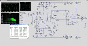
I have to comment about a little problem I had with the modified Ampslab C200 Siklay: I could not reduce bias current under 90mA which to me means low level oscillation. I swapped the outputs for the MJ15003/4 which are the recommended BJTs by the inventor, Mr Chua. No effect. Then I added the RC mod for the long input pair--> that allowed me to reduce I bias to 20mA. I went into tests with no increase in T° nor in I bias, so I got cruel, increasing stress, until, suddenly as it always is, the magic smoke went out: I fried all the output circuit from one of the channels....now we confirm why Siklay outputs are not that common....
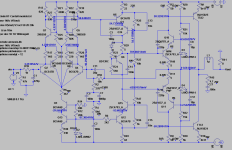
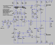
Back to the board. I thought about simplifying the input from cascoded CFP to simple cascode and adding ferrites to the emitter's resistors for the output CFP drivers'....just to end with a working amp, without going back to the stock amp, which sounds good but not as good as the LTMD amp...
I attach the schematics of the unstable amp and of the next step to try and stabilize it.
Soon, more news.
Cheers,
M.
I have to comment about a little problem I had with the modified Ampslab C200 Siklay: I could not reduce bias current under 90mA which to me means low level oscillation. I swapped the outputs for the MJ15003/4 which are the recommended BJTs by the inventor, Mr Chua. No effect. Then I added the RC mod for the long input pair--> that allowed me to reduce I bias to 20mA. I went into tests with no increase in T° nor in I bias, so I got cruel, increasing stress, until, suddenly as it always is, the magic smoke went out: I fried all the output circuit from one of the channels....now we confirm why Siklay outputs are not that common....
Back to the board. I thought about simplifying the input from cascoded CFP to simple cascode and adding ferrites to the emitter's resistors for the output CFP drivers'....just to end with a working amp, without going back to the stock amp, which sounds good but not as good as the LTMD amp...
I attach the schematics of the unstable amp and of the next step to try and stabilize it.
Soon, more news.
Cheers,
M.
Attachments

Hi Maxlorenz,
Yes - the problem with taming (oscillations) at Sziklai has been with "terrible" force for years!
But..... based on this particular circuit and with these particular transistors - no problems!
Best Regards
Trifonovaudio

Yes - the problem with taming (oscillations) at Sziklai has been with "terrible" force for years!
But..... based on this particular circuit and with these particular transistors - no problems!
Best Regards
Trifonovaudio
Thank you very much for your input.
I will try to dig into it further.
edit: oh yes, very interesting, you connect directly the emiter of the driver and use a R at the collector of the main output. Do you have the driver mounted also on the heatsink?
Best wishes,
M.
I will try to dig into it further.
edit: oh yes, very interesting, you connect directly the emiter of the driver and use a R at the collector of the main output. Do you have the driver mounted also on the heatsink?
Best wishes,
M.
All pre-end drivers are together with the end (power) transistors of the radiator(heatsink).
If you are asking about the temperature sensor Q 11 - there the answer is complex and not clear!
Depending on the implementation of "live" - after careful research we make a decision!
Cheers
Trifonovaudio
If you are asking about the temperature sensor Q 11 - there the answer is complex and not clear!
Depending on the implementation of "live" - after careful research we make a decision!
Cheers
Trifonovaudio
Good news:
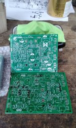
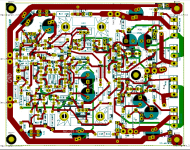
I decided to test the Hawksford FB CCS (again) but with proper PCBs....and they just arrived!
I put there the many "upgrades" that I love to add...I did it fast. I will optimize it later....I hope there are not errors.
I will test it, as soon as I finish with my many other experiments.
Cheers,
M.
I decided to test the Hawksford FB CCS (again) but with proper PCBs....and they just arrived!
I put there the many "upgrades" that I love to add...I did it fast. I will optimize it later....I hope there are not errors.
I will test it, as soon as I finish with my many other experiments.
Cheers,
M.
Attachments

Last edited:

Hi.
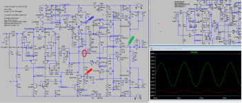
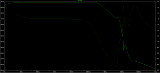
I noticed an interesting and puzzling effect when transforming a simple Miller Comp Cap. into a C-R subcircuit....I present an example of Cm= 82pF and Rm= 1K...the phase response is totally different (from my last strategy) and from 3megaHz up, it goes upwards and even gets positive, avoiding getting near -180°. The nearest it gets is -166° at +3dB though...😕
Any opinions are welcome.
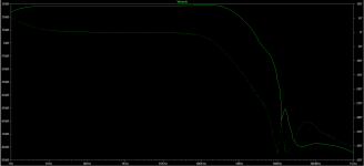
I also attached a conventional response....closed-loop....
Cheers,
M.
I noticed an interesting and puzzling effect when transforming a simple Miller Comp Cap. into a C-R subcircuit....I present an example of Cm= 82pF and Rm= 1K...the phase response is totally different (from my last strategy) and from 3megaHz up, it goes upwards and even gets positive, avoiding getting near -180°. The nearest it gets is -166° at +3dB though...😕
Any opinions are welcome.
I also attached a conventional response....closed-loop....
Cheers,
M.
Attachments
What's the mystery? The Сap comp of Miller limits the spectrum for the next stage, and the RC phase twists approximately in the range of 25-60 degrees at a frequency corresponding to its time constant, and the entire over spectrum goes to the next stage, if it does not have enough frequency properties, it simply turns the phase and the result is positive feedback.noticed an interesting and puzzling effect when transforming a simple Miller Comp Cap. into a C-R subcircuit....I present an example of Cm= 82pF and Rm= 1K...the phase response is totally different (from my last strategy) and from 3megaHz up, it goes upwards and even gets positive, avoiding getting near -180°. The nearest it gets is -166° at +3dB though...😕
Any opinions are welcome.
- Home
- Amplifiers
- Solid State
- The AMNESIS amp: a good amplifier, like a gentleman, has no memory