Yes, you are correct. I was trying to increase simulated stability margins (which everybody knows here that I do not understand 😛 ) and it ocurred to me this trick which seems to work both on virtual and practical settings: my Amp3 and VFET amp have driven rather thick speaker cables with no sign of overt instability. I look forward to your evaluation.accelerating link С11R45С27 implemented on the diagram of the second order, but in order to cover the entire correction range, and with Miller correction it is very wide, you need a slope of 6 dB per octave, and this is the first order, it’s hard for me to imagine what will happen to the transient response on a real load with a significant capacitive character , so this leads to a change in the phase angle and reduces the stability of the circuit, 2nd order Miller correction rarely has a large margin of stability, plus the R46 also relies on the amplifier output where the voltage is modulated for the boosttrap ...
There will be time, I will try to model this "abracadabra", there is a lot of "freak" in it, as it seems to me at first glance...
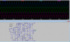
A plot of the present Darlington output.
Cheers,
M.
Attachments

Please note that these are voltage curves, as you know. In order to see the current curves I would have to include small Rs there.Interesting results M, no spikes at 20KHz. I am also working on a new CFP design. 😊
Do you need them or are we good like that?
Cheers,
M.
It is fine, I'm only interested to check on the output curves at the higher frequencies. I've also simulated some other popular cfp's (for DIY) and surprisingly it had 'those spikes' (cross over distortion? or possible sign of instability?..🤔) but these amps were actually stable in the real build! One with over 1Mhz ULGF and the other one with a conservative 700Khz ULGF. 'Those spikes' (see image attached) are none existent in an EF output stage.Please note that these are voltage curves, as you know. In order to see the current curves I would have to include small Rs there.
Do you need them or are we good like that?
Cheers,
M.
Now here's what I've experienced so far with cfp output topology, I built one using a differential VAS, ULGF was at 1.2Mhz. It oscillated the first time I powered it on, surprisingly the solution that effectively worked was to decrease ULGF and have plenty of gain margin of about 20dB. With my limited understanding the output stability may correlate with the over all topology used. My latest experimentation is using bootstrap 'a la' P3A but I'm pushing it to have a higher ULGF 'a la' Bigun's TGM8.
(Sorry M if my posting goes O.T.)
'Those spikes' mentioned above.
Attachments

Last edited:
I believe you can directly plot the base currents by changing the probe into a clamp meter. In the plot it will show I not V.Please note that these are voltage curves, as you know. In order to see the current curves I would have to include small Rs there.
Do you need them or are we good like that?
Cheers,
M.
(BTW I tried to simulate your sziklai output version but it asks for the amnesis.lib file).
Thank you, I have everything I need, what I don’t have is a practically implemented scheme in this topic. I see a complete mess with working points, (for example, Zeners do not work normally on weak currents - Ohm's law does not work for you either?Maybe you have to:
for the first time I hear that with the help of the skin effect they tried to stabilize something in the amplifier, well, maybe some losers, I don’t know ...amp have driven rather thick speaker cables with no sign of overt instability...
there is no practical scheme - there are no estimates ...I look forward to your evaluation.
Hi,Thank you, I have everything I need, what I don’t have is a practically implemented scheme in this topic. I see a complete mess with working points, (for example, Zeners do not work normally on weak currents - Ohm's law does not work for you either?
for the first time I hear that with the help of the skin effect they tried to stabilize something in the amplifier, well, maybe some losers, I don’t know ...
there is no practical scheme - there are no estimates ...
You may swap zeners for LEDs or other passive, if still of interest...
What currents do you look for when working with zener???
Cheers,
M.
I will try to upload it...NO wait! Just remove that directive and it will/must work just fine.(BTW I tried to simulate your sziklai output version but it asks for the amnesis.lib file).
This ouput I will try next. First time I tried it it sounded good, reminiscent of the AMpslab C200 Sziklai posted above, but there were some quirks that let me pospone it. The AMpslab C200 Sziklai with LTMD deserves its own thread: it sounds good and it is rather easy to build.
Cheers,
M.
Attachments
Last edited:
good suggestion - I support.Hi,
You may swap zeners for LEDs or other passive,
he-he, recommended in the datasheet...)))What currents do you look for when working with zener???
Henk.
P.S. In the attachment in the circuit, a correction capacitor of a very large capacitance of 330pF, do you have an approximate idea of much current the stage needs to pump such a large capacitance?
This is equivalent to the fact that the voltage amplifier stage operates on a resistance of about 2.7 kΩ at a frequency of 20 kHz, i.e. the output stage is actually shunted at the input for high frequency signals...
Last edited:
OK.
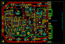
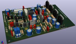
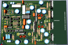
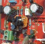
While I digest all of Hennady's spurs, I mannaged to include the latest "upgrades" to the future PCB (a real mess) with jumpers. Parallel caps must go on the bottom for the latest caps; not very elegant but it works OK.
Adding caps to the bootstraps produces a generous and exuberant sound, so I took the executive decision to keep them (at least in my amps with 32V supplies) and try to reduce the ill effects, like a somewhat "thick" sound with some recordings, with //good Q caps.
Cheers,
M.
Attachments


Hi all,
Now I come with a good perceptual description of adding Elcaps only to Mosfet's bootstraps: it is like pushing on the "loudness" button on your old classic receiver. 😀
I have not had the time to // Elcaps with my trustful 1uF WIMA MKPS4...I have a new project... 😛
I do not want to hijack de Ocampo's thread nor I want to cause Hennady there a collapse, so I will put here the sequence of AmpslabC200 "natural evolution".
The first 2 are already built. The last is on hold. You see I advocate the internal bootstrapping of the Drivers for the CFP in order that at least the Drivers see a low VCB (narrow jonction; Early?) which IME has an impact o good sound...but I have not tested it yet and my AmsplabC200.2 LTMD would be tricky to mod inside the Sansui box...
Last pic is the LTMD input mod... 😎
Cheers,
M.
Attachments
-
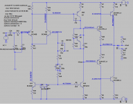 AMPSLABC200 Siklai.png22.8 KB · Views: 193
 -
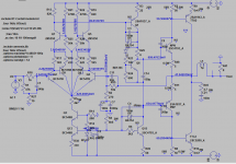 AMPSLAB C200.2 LTMD IN SZIKLAI OUT.png32.4 KB · Views: 182
 -
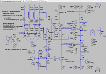 AMPSLAB C200 TMC2 cascodedDRIVER SZIKLAI.png35.7 KB · Views: 195
 -
 AMPSLAB C200.2 LTMD cascoded VAS Bootstrapped SZIKLAI out HIGH V.png37.1 KB · Views: 194
 -
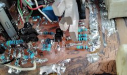 AMPSLABC200 LTMD MOD PIC.jpg134.2 KB · Views: 201
Last edited:
Hi Guys,
Here is to remind you how you can swap the input pair of your boring amp for the simplest Bootstrapped CFP to see if the reduction of the VCB/narrowing and equalization of the jonctions' widths/lowering the putative thermal memory distortion or whatever the physical explanation might be, has an impact on how you perceive/enjoy your favorite music...
Now, if you don't perceive any differences...maybe you are in the wrong hobby... 😆 😆 😆
I Love You All,
M.
Attachments
Guys,
I managed to parallel the bootstrap caps for the output Mosfets for Amp1 with good 1uF PEPT, Russian Millitary surplus film caps from Soviet era, which are 3.2cm X 1cm axial caps. This Amp1 has a wide and deep PCB from the original DX-Blame from Uncle Charlie (thanks Charlie, Rudi and Metal 🙂) so the caps were OK. The effect is great; even with low hours on them it is obvious the increase in refinement and softness, compared to raw Elcap alone, without loosing bass impact. I will be soon indulging you with a, I hope, nice audio recording...
I insist that all Bootstrap caps be //with good quality film caps before neglecting this ancient technique.
Cheers,
M.
Attachments
Hi max!Guys,
I managed to parallel the bootstrap caps for the output Mosfets for Amp1 with good 1uF PEPT, Russian Millitary surplus film caps from Soviet era, which are 3.2cm X 1cm axial caps. This Amp1 has a wide and deep PCB from the original DX-Blame from Uncle Charlie (thanks Charlie, Rudi and Metal 🙂) so the caps were OK. The effect is great; even with low hours on them it is obvious the increase in refinement and softness, compared to raw Elcap alone, without loosing bass impact. I will be soon indulging you with a, I hope, nice audio recording...
I insist that all Bootstrap caps be //with good quality film caps before neglecting this ancient technique.
Cheers,
M.
I think you should reduce the value of R22 and R25 to 220 ohms if possible. Or reduce C13 and C22 to 15uf.
Thank you!.
I have not performed this mod on my other amps yet. Would you care to elaborate?
I remember Henk prefers an even split of the voltage divider...
Cheers,
M.
PS: I haver yet to test the Bootstrap Caps tied to the power rails instead to output, for both the drivers and outputs, which gives 4 options... :-(
Not not mention film v/s Elco v/s parallel the former...
Last edited:
If the time constant (resistor X capacity) is too long, it will ''eat'' your high frequency.Thank you!.
I have not performed this mod on my other amps yet. Would you care to elaborate?
I remember Henk prefers an even split of the voltage divider...
Cheers,
M.
PS: I haver yet to test the Bootstrap Caps tied to the power rails instead to output, for both the drivers and outputs, which gives 4 options... :-(
Not not mention film v/s Elco v/s parallel the former...
Don't use electrolytic capacitor if possible. Use good film caps (mkp) . 👍 Don't use wima. Don't use ceramic or mica. (they distort). npo ceramics are ok. My 2 cents.
OK. Thank you. You maybe have given the clue of the "taylor made" and "bass boost" effect of playing with different values and qualities for the Bootstrap caps (why didn't I see that before?) , for example my Amnesis VFET had originally the main VAS Bootstrap 1K+1K with 15uF Vishay (-3db of 10.6KHz), which gave a very elegant and ballanced sound. I confess I like better the present arrangement of 150uF Elco + 15uF Vishay + 270nF polystyrene... 😳 because it gives a fuller sound with more weight-in-the-bass...
The good part is that you can adapt/adopt different strategies to match you particular system... 😛
I still have PETP and some good sounding Vishay film. They are big tho...
Now I have other projects going on but eventually I shall test these many options...
Cheers and buckle-up! 😀
M.
The good part is that you can adapt/adopt different strategies to match you particular system... 😛
I still have PETP and some good sounding Vishay film. They are big tho...
Now I have other projects going on but eventually I shall test these many options...
Cheers and buckle-up! 😀
M.
Last edited:
- Home
- Amplifiers
- Solid State
- The AMNESIS amp: a good amplifier, like a gentleman, has no memory.