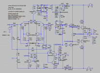
what is the reason for this connection? More precisely, the lack of common sense in such an inclusion?The next common-sensical move, which I had posponed, is to test the alternative connection of the bootstrap cap to the power rails, in steps.
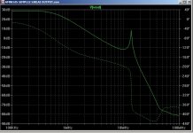
See the attached diagram. Corner F should be 23KHz or more...
I don't know this bass boost. Can you share the schematic please?You maybe have given the clue of the "taylor made" and "bass boost" effect of playing with different values and qualities for the Bootstrap caps
Yes it give good bass but if you need that trick it's probably to compensate a weakness in your system? (maybe your speaker are too weak in the bass freq, maybe your room is not really well adapted for listing music, too much reflection of high freq... Etc...)I like better the present arrangement of 150uF Elco + 15uF Vishay + 270nF polystyrene... 😳 because it gives a fuller sound with more weight-in-the-bass...
Sorry for the late reply.
Dear Hennady, please read: "the obvious next move for someone that has no knowledge of electronics but is willing to try options that at least work on simulation".
Note that sometimes the Intuitive Mind let me try paths that end in "failure" just to learn more...as you may know, failures often teach more than successes... 😀
I now remember that years ago I connected a film cap in similar fashion (from memory) and I got the biggest explosion to date!
Those were the times when the amp had a little tendency to oscillate...😛 I should have produced a BIG voltage peak since the cap was something like 250V...I think... Maybe I should dedicate myself again to power generators...
Dear Mad,
I use to try mods on different of my five system, and no, the speaker have good bass.
"Bass boost" is the most accurate description for the audio effect of connecting an Elco as bootstrap cap, I would say either on VAS, driver and/or output sections.
Too many interests and projects going on...no will to mod yet.
Cheers,
M.
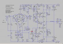
I found that old post, but the driver's cascode BJT also exploded with the film cap. I attached a schematic that more or less represents that old experiment, from memory...
Remember one channel had bursts of oscillation on power peaks???
Fortunatelly I remembered that Dr. Leach on his Low TIM amp and Uncle Charlie on his Blame ES, recommended connecting the Zobel from output to ground ... on the speakers' binding posts. The reason being that due to packed layout that subcircuit can introduce positive feedback that can exite the input through signal ground. (edited)
Remember the 1uF cap that decouples the base of the cascodying T for the outputs? Connecting one of them to the oscillating amp produced the biggest instantaneous explosion of the cascodying BJTs for the drivers! (here I forgot to mention that the cap also exploded in an spectacular fashion) The rest of the BJTs survived. That was when I reduced the biasing for the cascodying elements of the driver section to 3,6V because LT spice whowed nice curves...
Cheers,
M.
Attachments

Re-viewing the simulations for that alternative connection, in this particular computer, do not seem quite good: in one schematic it shops the outputs and in other the Vout ramps-up shortly as if "charging" the caps...maybe it is better to follow Henk's implicit advise... 😊what is the reason for this connection?
For those interested but refrained by my output section experiments, remember the LTMD circuit can be tasted in its simple form with EF output. See attachments...
Simulations on LTSpice do not support the warning from dear Mad. On the contrary, a too small cap will reduce bass contribution of the bootstrap, or that is what I understood...for example 1K+1K resistor combination needs 33uF cap to be flat to 20KHerz...that supports my finding of an elegant but lean sound with a 15uF Vishay cap.
I am looking for energy and will to insist on my Siklai output amp. The thing is that I am now experimenting with building my own Power Transformers: very entertaining stuff...
Cheers,
M.
Attachments
Hello. A small modification.
Wow! Thank you.
Would you care to elaborate?
I never had the courage to DC connect the FB...
Very interesting but not Amnesis anymore: in order to be faithful to Hephaïstos' and Peufeu's work we have to have a bootstrapped CFP at the input.
I propose another modded version and a SIMPE CFP output...I hope I got it right.
Cheers,
M.
PS: the Siklai output version needs a higher overload protection at the VAS to allow a bigger headroom, sorry...
Attachments
Last edited:
In your modification, the C3 R19 chain and anti-clip diodes are turned on illogically, in this embodiment they only reduce the upper frequency of the current mirror, due to which its capacitance becomes more dependent on the signal level, Next, you have a second-order Miller correction on a single-stage cascode VAS element, this is a very unstable solution, because even the capacitance of the circuit board will be affected. ...A small modification.
Please dear Hennady, propose your best solutions, IF it is worthy of doing.In your modification, the C3 R19 chain and anti-clip diodes are turned on illogically, in this embodiment they only reduce the upper frequency of the current mirror, due to which its capacitance becomes more dependent on the signal level, Next, you have a second-order Miller correction on a single-stage cascode VAS element, this is a very unstable solution, because even the capacitance of the circuit board will be affected. ...
Thanks very much,
M.
It's worth a lot.IF it is worthy of doing.
If the amplifier were soldered in practice, then they would never use a capacitance C14 with a nominal value of 150 microfarads in the multiplier circuit !!! It's just that the simulator forgives you everything ...
As for the C3R19 circuit, if you think at least a little bit, then in your circuit you can see that it closes the Base-Collector transition of the current mirror, because in the case of an axial voltage output from the input stage stage, the correction circuit closes either to ground or to the power bus, in In your case, this is a negative supply voltage. By the way, in the simulator, such an ugly connection should be visible in the parameters.
you can do nothing for the simulator and so it will do ... )))
This is very correct, because. with progressive correction, the author of the simulation fails.Leave one 100pf capacitor in the shikai circuit .
Thank you all for your comments.
I will consider and study them in due time.
M.
I will consider and study them in due time.
Thank you Hennady. I confess I put 150u everywhere simply because I bought a big surplus lot years ago. What do you recommend?If the amplifier were soldered in practice, then they would never use a capacitance C14 with a nominal value of 150 microfarads in the multiplier circuit !!!
M.
Last edited:
Yeah, dismiss the last schematics. they were done on haste on another computer. I re-post my last Siklai, without C14.Leave one 100pf capacitor in the shikai circuit . Otherwise, the frequency response has an ugly look.
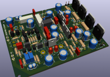
BTW, I started populating the PCB for this amp, but with BC548/558 as input CFP.
Cheers,
M
Attachments
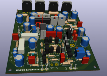
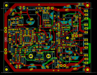
I decided to shrink my new PCB to 126*100mm, because I realized that I have a satisfactory mechanical support with it with my strategy. I managed to put in the "heat-sink decoupling" (just need a couple of cuts) and both bootstrap caps, the output's ones being optional through a jumper. The parallel film caps for these will have to go under the PCB. Not elegant but effective, and good sounding.
The central output BJTs will go upright with their own little HS connected to central ground. As always, output filters/Zobel go outside the board...
Guys, the Vref for the Cascoded VAS cannot be lower than 3V6 (in my case 4V: 2X Yellow LEDs) as the voltages collapses when tested with 2V88 blue LEDs...
Cheers,
M.
PS: I'll post later my Siklai Output adventures...
Attachments
put a 0.1 - 0.22 microfarad film capacitor.Thank you Hennady. I confess I put 150u everywhere simply because I bought a big surplus lot years ago. What do you recommend?
It's right.Yeah, dismiss the last schematics. t
the circuit is still also poorly modelled.I started populating the PCB for this amp
As always, output filters/Zobel go outside the board...
firstly, this circuit does you not correspond to the Bushe equation, and judging by the illogical conductors layout of the printed circuit board, you should leave Zobel just on the printed circuit board.
Dear Hennady,put a 0.1 - 0.22 microfarad film capacitor.
It's right.
the circuit is still also poorly modelled.
firstly, this circuit does you not correspond to the Bushe equation, and judging by the illogical conductors layout of the printed circuit board, you should leave Zobel just on the printed circuit board.
Thanks you for your kind recommendations. It is nice when you propose a better solution. It would be even better if you take the time to briefly explain the motifs of said solutions...you surelly understand that some of us won't go into a University to study Electronic Engineering just to play with out Hobby...but may be we will understand the technical explanations...
Cheers,
M.
Happy and Prosperous New Year to you all!
More adventures from your humble narrator...
You might remember that I explored a Siklai output Amnesis (moddying an ALLBJT QUAD) which was successful (with slow output BJTs) but had a scratching noise from time to time (apparently not due to oscillation) and sounded rather good...later, I suspected the noises came from the (cascoded with LEDs) input and I upgraded it to a JFET based bootsdtrapped2 input CFP which removed all noises.
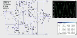
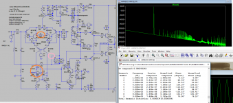
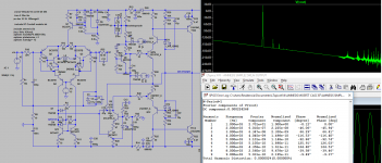
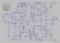
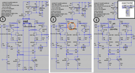
At the time of the builds I was short on P JFETs so 2 more amps have that cascodying with BJTs (see diagram n°1) where 1 (of 4) of the channels started to make similar noises, so I decided to eliminate that approach (which sounded great to me) passing through a simple (non cascoded) hybrid CFP ( diagram n°2) and then to the (now) preferred Bootstrapped2 input CFP (diagram n°3). When I got rid on ancillary sub-circuits and jumped from E to C for the BJT (quick and dirty mod) the sound became rounder and with more flesh but lacked refinement especially in the highs, with a raw and even grainy quality to it. I waited a little for the soldering (lots of it) to burn-in but with only a small improvement. I supposed high THD and decided to change strategy: what better scenario to explore Printnik's recommendation of an inductor (diagram n°2), which has the potential to reduce THD by one, maybe two orders of magnitude...
Gentlemen, I hate to speak the words that you all fear: the sound totally changed!
Even when I first tried with a big 10mH (I have a bunch for another project) it became refined, soft, extended, both on the highs and on the lows, attacks became crisp and with a nice curve, very seductive, on par IF NOT BETTER than the VFET Amnesis! The "suspend disbelief" effect is ON. So very worthy of further exploration.
The adverse effects were: sound is felt as lighter; one of the channels went from silent to buzzing!
Second experiment was with a DIY 10uH air-core inductor: totally unstable amp!
Then I remembered that I was gifted with an old but good quality VHS player which I gutted and which had many good quality inductors of the dipped kind. I tried in descending order from 2.4mH, then 560uH, 470uH, 270mH until 120uH where one of the channels became unstable. Always with comparable results, sound-wise. In fact, I have to make extended listening test to evaluate if there is a difference in sound with different values at all...the square wave test is awful though! 😆 I have more experiments planned. 😎
That's all for now. A very seductive, organic, etheric sound. Thanks again dear Printnik and no I have not implemented the anti// diodes yet and I cannot figure out its purpose (simulation do not show change) at all,
Cheers,
M.
More adventures from your humble narrator...
You might remember that I explored a Siklai output Amnesis (moddying an ALLBJT QUAD) which was successful (with slow output BJTs) but had a scratching noise from time to time (apparently not due to oscillation) and sounded rather good...later, I suspected the noises came from the (cascoded with LEDs) input and I upgraded it to a JFET based bootsdtrapped2 input CFP which removed all noises.
At the time of the builds I was short on P JFETs so 2 more amps have that cascodying with BJTs (see diagram n°1) where 1 (of 4) of the channels started to make similar noises, so I decided to eliminate that approach (which sounded great to me) passing through a simple (non cascoded) hybrid CFP ( diagram n°2) and then to the (now) preferred Bootstrapped2 input CFP (diagram n°3). When I got rid on ancillary sub-circuits and jumped from E to C for the BJT (quick and dirty mod) the sound became rounder and with more flesh but lacked refinement especially in the highs, with a raw and even grainy quality to it. I waited a little for the soldering (lots of it) to burn-in but with only a small improvement. I supposed high THD and decided to change strategy: what better scenario to explore Printnik's recommendation of an inductor (diagram n°2), which has the potential to reduce THD by one, maybe two orders of magnitude...
Gentlemen, I hate to speak the words that you all fear: the sound totally changed!
Even when I first tried with a big 10mH (I have a bunch for another project) it became refined, soft, extended, both on the highs and on the lows, attacks became crisp and with a nice curve, very seductive, on par IF NOT BETTER than the VFET Amnesis! The "suspend disbelief" effect is ON. So very worthy of further exploration.
The adverse effects were: sound is felt as lighter; one of the channels went from silent to buzzing!
Second experiment was with a DIY 10uH air-core inductor: totally unstable amp!
Then I remembered that I was gifted with an old but good quality VHS player which I gutted and which had many good quality inductors of the dipped kind. I tried in descending order from 2.4mH, then 560uH, 470uH, 270mH until 120uH where one of the channels became unstable. Always with comparable results, sound-wise. In fact, I have to make extended listening test to evaluate if there is a difference in sound with different values at all...the square wave test is awful though! 😆 I have more experiments planned. 😎
That's all for now. A very seductive, organic, etheric sound. Thanks again dear Printnik and no I have not implemented the anti// diodes yet and I cannot figure out its purpose (simulation do not show change) at all,
Cheers,
M.
Attachments
Last edited:
- Home
- Amplifiers
- Solid State
- The AMNESIS amp: a good amplifier, like a gentleman, has no memory.