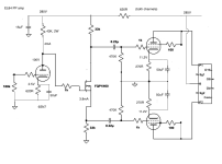
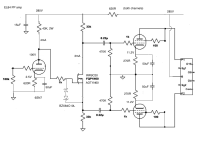
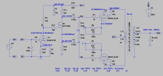
For maximum headroom you want the gate of the MOSFET to be about one quarter of the supply voltage. The MOSFET PI can then swing almost half the HT at each output.How do you calculate the design?
However, you're only driving EL84s which need what, ~30Vpp from each PI output? So you need only a bit more than 30V across the MOSFET at idle as a bare minimum, say 40V as a round number. So your gate voltage can be as high as:
(HT-40V)/2
Crss for the DN2540 is 5pF max, so Miller capacitance will be <10pF, but Cgs adds another few picofarads. Let's say 30pF total input capacitance on a really bad day, which is not much capacitance! R16 is what is clobbering your bandwidth, rather than the MOSFET. But all you need to do is add a compensation capacitor across R16 and you can completely cancel it out and make the bandwith plenty wide. You'll probably have to adjust the cap on test though.Do you have an idea why is the DN2540 is so bad? Capacitances?
Last edited:
Mostly.Do you have an idea why is the DN2540 is so bad? Capacitances?
Dynamic gate capacitance is about 200-300pF at low/er/ DS voltage.
It has low transconductance, which "helps" compensate Ciss.... if it's enough large... but not in case of this FET.
See Ale's blog:
https://www.bartola.co.uk/valves/2016/01/09/slew-rate-part-iv-and-source-followers/
This device has -enough- good behaviour, if you use as /cascode/ CCS, but not as VAS. This is my experience.
That looked familiar then I realised it's my design 🙂 . The 350V supply was regulated (I used a Maida regulator), R23 was a trimpot adjusted to get the desired anode voltage on the EF184 which also sets the phase splitter operating point. I used it for several years but currently stripped down waiting for a rebuild into something else.
.
Should we wait for your new and improved design? 😀 How did the previous one sound/work out?I used it for several years but currently stripped down waiting for a rebuild into something else.
If you don't want gain, a 1:1 bridging transformer, 10K:10K like a Jensen, with two matching resistors on secondary to ground to form a virtual center tap takes care of the phase splitting duty. And you get the options of balanced or unbalanced input without affecting gain. Perfectly symmetrical. The downside is that you'll need two 26 tubes for PP.
Last edited:
Nothing wrong with the old one, sounded great. I replaced it with a hybrid mosfet/tube amp (Tubecad's supertriode arrangement) that gave me more power. I'm not one to build amps just for the sake of it (how many do you actually need?!) so I plan to use the old one as a testbed for new ideas. But life keeps getting in the way of frivolous hobby activities 😁Should we wait for your new and improved design? 😀 How did the previous one sound/work out?
Thanks Merlin!Crss for the DN2540 is 5pF max, so Miller capacitance will be <10pF, but Cgs adds another few picofarads. Let's say 30pF total input capacitance on a really bad day, which is not much capacitance! R16 is what is clobbering your bandwidth, rather than the MOSFET. But all you need to do is add a compensation capacitor across R16 and you can completely cancel it out and make the bandwith plenty wide. You'll probably have to adjust the cap on test though.
I did indeed not pay attention to the voltage divider in front of the DN2540, now I am happy again 🙂
Erik
I like Mogliaa's work a lot, this post was indeed the one that I had some troubles with, as he seems to forget that transconductance is related to the actual current through the device, and he does not seem to actually measure the transconductance for the enhancement device. But indeed, cascoded devices work even better.Mostly.
Dynamic gate capacitance is about 200-300pF at low/er/ DS voltage.
It has low transconductance, which "helps" compensate Ciss.... if it's enough large... but not in case of this FET.
See Ale's blog:
https://www.bartola.co.uk/valves/2016/01/09/slew-rate-part-iv-and-source-followers/
This device has -enough- good behaviour, if you use as /cascode/ CCS, but not as VAS. This is my experience.
I was shortly "worried" about the DN2540, or fets in general, having too bad HF performance. Revintage and Merlin pointed towards the voltage divider in front of it as a cause for the poor HF. I remember the discussion I had with a guy that compared a pentode with a DN2540 as VAS, and complaining about the HF of the DN2540. I asked for the schematic, and he was feeding the mosfet from a 500k volume pot....
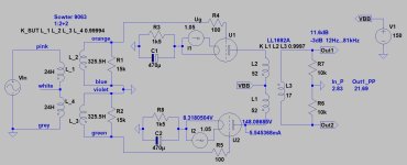
With two 26's can you also do paraphase or SE+concertina without need of transformers.If 2V RMS input is important, the 1:2+2 SUT + PP line transformer loaded #26 tubes is satisfactory solution.
Sample:
View attachment 1286541
I've had a change of plan. The amp in question is a Leak Stereo 20 so I'm going back to a generic PP EL84 amp with an input stage (not 26) for which there are loads of schematics. I would use it in triode output or maybe UL. Start without global feedback. I like the idea of a mosfet splitter so there's no h-k voltage issues and I can use a straightforward double triode on the input. So I'm thinking a 6SN7 DC coupled to a mosfet splitter. I'll go back through this thread to see if there's a design here I can copy. But it would help me if you guys could post a design with a 6SN7. B+ would be about 280V.
The Leak Stereo 20 chassis imposes restrictions, but for a later PP build on a new chassis I would indeed use a 26 front end and either a PPP output stage or a larger valve in PP. So everything in the thread is relevant.
The Leak Stereo 20 chassis imposes restrictions, but for a later PP build on a new chassis I would indeed use a 26 front end and either a PPP output stage or a larger valve in PP. So everything in the thread is relevant.
That looked familiar then I realised it's my design 🙂 . The 350V supply was regulated (I used a Maida regulator), R23 was a trimpot adjusted to get the desired anode voltage on the EF184 which also sets the phase splitter operating point. I used it for several years but currently stripped down waiting for a rebuild into something else.
Thanks @tikiroo. I`m gonna test that schematic.🙂
Just above 75 V over the FET.What would be the voltages on either side of the mosfet?
. . . could the Hammond 1140-LN-C, which we have both used "in reverse" as a 1:4 SUT be used to invert phase and, to keep it unity gain, just add a voltage divider on the outputs?
Looks like my earlier suggestion would be possible.Yeah, looking again I see that using SUT mode with that model wouldn't work because the single primary becomes the secondary. I guess you just need one with dual secondaries which can then supply one in-phase and one "out of phase" / opposite phase to the output tubes.
Or would it be possible to create an artificial center tap on the secondary??
The Jensen schematic shows an artificial CT being used to invert phase so the Hammond could be configured as a 1:4 SUT and the resulting single secondary could be wired the same way.
Then just add a stereo volume pot between the inverted outputs and the grids of the 26s, or whatever tube you like. This would allow you to adjust the output from the input transformer from less than 1:1 up to 1:4.
Or am I missing something?
- Home
- Amplifiers
- Tubes / Valves
- Phase splitter choices on input of PP amp


