Hi Andy, many MOSFETs but only depletion should be used here.
Pblix , do not treat MOSFETs as a triodes as they all have pentodelike characteristics. Though they will get triode curves if you use Schade feedback. LND150 is good if you only use them up to a few ma.
Pblix , do not treat MOSFETs as a triodes as they all have pentodelike characteristics. Though they will get triode curves if you use Schade feedback. LND150 is good if you only use them up to a few ma.
I've had a change of plan. The amp in question is a Leak Stereo 20 so I'm going back to a generic PP EL84 amp with an input stage (not 26) for which there are loads of schematics. I would use it in triode output or maybe UL. Start without global feedback. I like the idea of a mosfet splitter so there's no h-k voltage issues and I can use a straightforward double triode on the input.
OK, I see you have a plan then. Good luck with it, happy Mosfetting...
As you can see in #28 post, with enhancement FETs working too.Hi Andy, many MOSFETs but only depletion should be used here.
Pblix , do not treat MOSFETs as a triodes as they all have pentodelike characteristics. Though they will get triode curves if you use Schade feedback. LND150 is good if you only use them up to a few ma.
Good point, but in circuits with unity gain (such as a concertina phase inverter) it's irrelevant for all intents and purposes. With Shade you can get a MOSFET to act exactly as a triode as described here, down to overload characteristics. The article discuss JFETs, but works like a champ with MOSFETs too.Hi Andy, many MOSFETs but only depletion should be used here.
Pblix , do not treat MOSFETs as a triodes as they all have pentodelike characteristics. Though they will get triode curves if you use Schade feedback. LND150 is good if you only use them up to a few ma.
I disagree with the notion that only depletion mode MOSFETs are suitable. Adding a resistor from B+ to gate is easy enough, and there is your bias (consider adding a coupling cap to protect your source too). I like STQ2HNK60ZR. I started using it for two reasons: 1) it was available at the end of Covid when the world supply of LND150 dried up completely, and 2) it has internal protection zeners that LND150 lacks. Please note though that it is enhancement mode and also not pin-compatible (if memory serves) with LND150. It also comes with higher capacitances that can cause reduced bandwith, so be warned. I've used it "Trioderized" and it is completely transparent, even as a gain stage with gobs of feedback.
With direct coupling to the VA stage, either enhancement or depletion devices can be used. If using capacitor coupling, a depletion device makes the biasing easier. NMOS typically, although using PMOS with direct coupling allows the VA to operate at ~2/3 of B+ instead of ~1/3 B+ if the tube you choose operates better with higher voltage. Choose a device with suitable power and current rating and low Crss. Smaller devices (e.g TO-92) are typically better in this regard if they have sufficient power rating, otherwise TO-220. There is another thread somewhere for mosfet source followers where people suggested various options.
Hi @andyjevans, I see mu values mentioned, but what is the maximum gain that is acceptable for the first stage? Apologies if it is already mentioned, could not find it.
I tend to calculate by the mu of the valve in question. I shoot for a combined mu of around 140 to 200 in my own system. So the EL84s in triode are mu=20, therefore the driver valve would ideally be around mu=7 to mu=10. In my SE amps with EL12 outputs I use a 26 DHT which gives me 18 x 8 = 144. So the ideal EL84 driver for me would be the 37, so 9 x 20 = 180. The 76 or 6P5 would be 13.8 x 20 = 276 which is a bit higher than I like but OK. The 6J5 would give 20 x 20 = 400 which gives too much unnecessary gain.
Add about 2-3 dB for driver gain as headroom.
For example if #76 gain stage has 20dB gain and EL84 bias is 11V, up to A1 limit (capacitor coupled power stage working in AB mode), the 1.1V peek input is enough.
For example if #76 gain stage has 20dB gain and EL84 bias is 11V, up to A1 limit (capacitor coupled power stage working in AB mode), the 1.1V peek input is enough.
The stage gain depends on the valve u, but also on the plate resistor. You can have a 6SN7 stage with a gain of~10. It will be rich in 2H, but those will get mostly cancelled in the PP output stage.I tend to calculate by the mu of the valve in question. I shoot for a combined mu of around 140 to 200 in my own system. So the EL84s in triode are mu=20, therefore the driver valve would ideally be around mu=7 to mu=10. In my SE amps with EL12 outputs I use a 26 DHT which gives me 18 x 8 = 144. So the ideal EL84 driver for me would be the 37, so 9 x 20 = 180. The 76 or 6P5 would be 13.8 x 20 = 276 which is a bit higher than I like but OK. The 6J5 would give 20 x 20 = 400 which gives too much unnecessary gain.
You could use your LN1140 in step-down 4:1 as phase splitter. Then you could have more options like ECC40, 6N7 etc...I tend to calculate by the mu of the valve in question. I shoot for a combined mu of around 140 to 200 in my own system. So the EL84s in triode are mu=20, therefore the driver valve would ideally be around mu=7 to mu=10. In my SE amps with EL12 outputs I use a 26 DHT which gives me 18 x 8 = 144. So the ideal EL84 driver for me would be the 37, so 9 x 20 = 180. The 76 or 6P5 would be 13.8 x 20 = 276 which is a bit higher than I like but OK. The 6J5 would give 20 x 20 = 400 which gives too much unnecessary gain.
Can you give me an example of a 6J5/6SN7 with a gain of 10? How is this achieved. Thanks.The stage gain depends on the valve u, but also on the plate resistor. You can have a 6SN7 stage with a gain of~10. It will be rich in 2H, but those will get mostly cancelled in the PP output stage.
Something like this. You basically reduce the plate resistance to reduce the voltage swing. It is not ideal, and result in high 2H, which should be mostly compensated in the output stage. You may try listening to it.

Unbypassed cathode resistor. Mu is the upper limit (with infinite load) and one can always dial the gain down by lowering the plate load, degenerating gm, or both.Can you give me an example of a 6J5/6SN7 with a gain of 10? How is this achieved. Thanks.
Another example of gain around 10 could be the 6SN7 LTP with current source in the tail. For current source you could easily use a suitable pentode or even a triode that results in about 100K or more effective tail resistance.... No sand!! Sand only necessary if you don't have 110-120V supply to spare.Can you give me an example of a 6J5/6SN7 with a gain of 10? How is this achieved. Thanks.
Last edited:
If you want to run the 6SN7 linearly, say no less than 5-6 mA per triode, the resistor cannot be big. For 10mA (5+5 mA) a 22K resistor will result in 220V drop!! Even a triode can do better than 22K with much less voltage required. A modest ECC82 with 130-140V supply can easily result in about 50K if the right cathode resistor (for the ECC82) is used (2.2K should be enough). Then only need a partition network to bias the ECC82 correctly.
Great initiative! Suppose you will try them in the complete power amp circuit, as a lot of distortion cancellation will be involved? Why not also try them, with or without bypassed cathode cap?
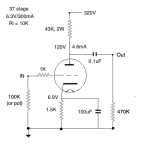
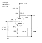
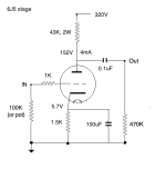
So today I tried out in my line stage:
The 37 was slightly the best of them (I think...).
The 6P5GT and 76 were practically the same sound with a little more gain
The 6J5GT round plate were very close again
The 6J5GT flat ribbed plate were less good - flatter and less immediate.
Findings show that all the round plate tubes sounded similar, and in terms of construction they are indeed similar. And the round plates sounded better than the flat ribbed plates, which I expected from previous A-B comparisons of plate structures. What was encouraging was that directly after a 26 line stage most of the audio quality was there, if not quite the effortless smoothness and presence of the 26.
So now I have to decide whether to fit UX5 or octal sockets to the Stereo 20 amp. Advantage of octals - there will never be a shortage of 6J5s, though the preferred 6P5GTs are starting to become hard to find. Advantage of UX sockets are that the best sound came from the 37 and 76, though the 6P5 was very close. The gain of the 37 is the most suitable, though the 76 works as well. So a UX5 socket would allow a useful switch between the two tubes depending on the gain required and the availability of the tubes.
I should also include the fact that my volume control is digital, in software on my Mac Pro running iTunes from archived CDs. So the 37 needed almost no attenuation, the 76 a little more and the 6J5 significantly more. This could partly account for the slightly fresher sound of the 37s.
The sound I'm getting out of this line stage is better than I expected, and justifies all the good reports I've read about the 37 and 76, and indeed it's close relations the 27 and 56 running off 2.5v filaments. I could also try the 6V6 in triode, and I'll look at that next, though it would be at relatively low current. I think that at 5mA the present 43K anode resistor and the 1.5K cathode resistor might just work. We'll see.
- 37
- one 6P5GT and one 76 (waiting for more to arrive)
- 6J5GT round plate
- 6J5GT flat ribbed plate
The 37 was slightly the best of them (I think...).
The 6P5GT and 76 were practically the same sound with a little more gain
The 6J5GT round plate were very close again
The 6J5GT flat ribbed plate were less good - flatter and less immediate.
Findings show that all the round plate tubes sounded similar, and in terms of construction they are indeed similar. And the round plates sounded better than the flat ribbed plates, which I expected from previous A-B comparisons of plate structures. What was encouraging was that directly after a 26 line stage most of the audio quality was there, if not quite the effortless smoothness and presence of the 26.
So now I have to decide whether to fit UX5 or octal sockets to the Stereo 20 amp. Advantage of octals - there will never be a shortage of 6J5s, though the preferred 6P5GTs are starting to become hard to find. Advantage of UX sockets are that the best sound came from the 37 and 76, though the 6P5 was very close. The gain of the 37 is the most suitable, though the 76 works as well. So a UX5 socket would allow a useful switch between the two tubes depending on the gain required and the availability of the tubes.
I should also include the fact that my volume control is digital, in software on my Mac Pro running iTunes from archived CDs. So the 37 needed almost no attenuation, the 76 a little more and the 6J5 significantly more. This could partly account for the slightly fresher sound of the 37s.
The sound I'm getting out of this line stage is better than I expected, and justifies all the good reports I've read about the 37 and 76, and indeed it's close relations the 27 and 56 running off 2.5v filaments. I could also try the 6V6 in triode, and I'll look at that next, though it would be at relatively low current. I think that at 5mA the present 43K anode resistor and the 1.5K cathode resistor might just work. We'll see.
- Home
- Amplifiers
- Tubes / Valves
- Phase splitter choices on input of PP amp


