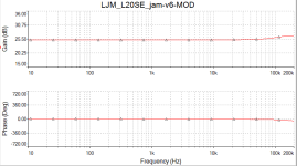
you have positioned the R1C1 input filter incorrectlyThis is my MOD of the original L20SE (with the real Toshibas TTC5200 and TTA1943). The multisim file is attached to this post.
Attachments

Bad boy, manners, manners.Very poetic, if it weren’t so sad to read this. (...) you can find the answer by delving into your "old school", is all just...
You're a little bit too aggressive, aren't you?
You are right. A "Persian flaw" ? In fact the buit amplifier has R1 before C1. I attach the correct files.you have positioned the R1C1 input filter incorrectly
Attachments
Hi,
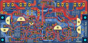
the L20SE kits had been delivered from china. I measured the output transistor holes and the mechanical holes to get them similar to the original pcb. Well done, i think.
I made little changes on my pcb to get some copper lines shorter, moved a transistor and capactitor and other little things.....finished and uploaded now. jlcpcb...
Exciting to me 🙂
I made two 4µH coils on a 26 mm kukident roll. 🙂
I have got all teeth...kukident is needful for the toilet...and for copper coils 😎
Greetings
Peter
Attachments
![IMG_20240212_193222[1].jpg](/community/data/attachments/1180/1180367-8773aaf45509df956bd42a290fbf7fce.jpg?hash=h3Oq9FUJ35)
Last edited:

1. Regarding the input filters (also called High Pass filters, or just HP filters):The input and output filters operate outside the 20-20 kHz frequency range of your best DAC.
- In order to to push the input cutoff frequency below 2 Hz the HP filter must consist of a 5-µF coupling capacitor. These are either electrolytics (with all their problems), or bulky and expensive film capacitors like, for instance, Wima MKP 10.
But, there are well known reasons not to use them:
- "First, because all practical HP filters progressively delay low frequencies relative to the rest of the music. Every added HP filter pole only adds to this ‘signal smearing’ [10]. Simulation in time and frequency domains shows this [11]."
- "Second, because HP filters require the use of capacitors. Capacitors that are almostideal for audio and not outrageously expensive and bulky, are limited in type and
values. Capacitors which are Faradically large enough not to cause substantial ‘signal smearing’ are in practice medium type electrolytics, and not in practice nor in theory anywhere near so optimal for audio as other dielectric types. - "For these reasons, even routine HP filtering (alias DC blocking or AC coupling) may be absent altogether."
Electrolytics are simply not that bad, -110dB or below isn't that hard to achieve as DC-blockers, especially with bipolar electrolytics. And given their very wide tolerance bands you can't really use them for anything but decoupling and DC-blocking where they can perform fine.
- "Second, because HP filters require the use of capacitors. Capacitors that are almostideal for audio and not outrageously expensive and bulky, are limited in type and
values. Capacitors which are Faradically large enough not to cause substantial ‘signal smearing’ are in practice medium type electrolytics, and not in practice nor in theory anywhere near so optimal for audio as other dielectric types.
And for an audio HP active filter all you need is somewhere around 220nF to 470nF film caps, no need for larger values that might necessitate electrolytics or even bulky film caps. Cut-off frequency around 15 to 20Hz is usually involved, not 2Hz. That's DC-blocking territory where precision in capacitor values isn't needed and you just use a large electrolytic.
The ones you really have to avoid are high-K ceramic - I've seen fake film caps that have a X7R ceramic hidden inside for instance - get caught out by those and your 0.0001% distortion filter suddenly becomes more like 0.1% or worse...
Hum... no. I am referring to the capacitor that goes in series with the input R1 resistor an for that one you need at least 2.2uF and even then it leaves a "dent" near 20 Hz.And for an audio HP active filter all you need is somewhere around 220nF to 470nF film caps
That's a passive filter, a DC-blocker, not an active filter requiring an exact response. Just use a large value to keep voltage across the cap low in the audio band.
Hum... let's see:
"With a 20 kR input return resistor, a 5 µF coupling capacitor is required to push the input cutoff frequency below 2 Hz. This capacitor should be of very high quality."
source: pg. 155, Designing Audio Power Amplifiers, Bob Cordell, 2011, ISBN: 978-0-07-164025-1
The formula for frequency cut-off is fc = 1/(2*Pi*R*C) Hz.
In the L20SE, the return resistor is the 10K R2.
So, to achieve the desired cut-off frequency below 2 Hz, the coupling capacitor should be 8 uF (cut-off: 1,98943678864869 Hz).
To avoid electrolytics you would have to either use multiple expensive/bulky PP/Polypropylene, or look at the less than optimal PET/metallised polyester (not exactly the realm of "this capacitor should be of very high quality").
Just use 100uF electrolytic, job done, low distortion, cheap cap. At 20Hz the cap has < 1% of the input voltage across it, so whatever distortion it has is reduced 40dB, and the voltage across it is minimal in the first place.
To be more precise 6.8uFIn order to to push the input cutoff frequency below 2 Hz the HP filter must consist of a 5-µF coupling capacitor.
That's right, that's exactly what I usefilm capacitors like, for instance, Wima MKP 10.
not true, because The cutoff frequency should be lower by at least an octave, or even better by 10 times i.e. at a frequency of 2Hz. This is due to a change in phase.Cut-off frequency around 15 to 20Hz is usually involved, not 2Hz.
It's good that you're reading Ben Duncan, read it again.source: pg. 65, High Performance Audio Power Amplifiers, Ben Duncan, 1997, ISBN 0 7506 2629 1
not a good idea, with such a large capacitance without polarization I would not recommend using an electrolytic capacitor. A metal film capacitor with a capacity of 6.8 μF or 10 μF is sufficient at the input node.Just use 100uF electrolytic,
You just can't resist, can you?It's good that you're reading Ben Duncan, read it again.
In science, when we express an opinion, we have to back it up with published, verifiable work. Unfortunately, science does not seem to be your strong point, so you keep forgetting to back up your claims.
unfortunately it only seems to youUnfortunately, science does not seem to be your strong point,
This is a forum, not science, I’m not going to teach you anything, you either agree or move on...so you keep forgetting to back up your claims.
P.S. "abracadabra" on your avatar - is that your name? ))))
I apologise for the distress, offence and disturbance my questions and comments have obviously caused you.unfortunately it only seems to you (...) This is a forum, not science, I’m not going to teach you anything, you either agree or move on...
I'm sorry to have troubled you.
Yes, it is my real name, rolled by a simple cipher. And regarding the picture in the avatar, yes, I am a real doctor (MD) and HIFI and audio DIY has been my hobby for the past 45 years (I am old, but still have very good hearing).P.S. "abracadabra" on your avatar - is that your name? ))))
Last edited:
Therefore, treat my comments on the diagrams as text encrypted by specialized education...Yes, it is my real name, rolled by a simple cipher.
very good, therefore, over 45 years of audio hobby, one could hear by ear all the nuances of amateur radio design and the use of reactive element ratings, especially in simple amateur radio circuits...but still have very good hearing
Capacitor Performance:
Source: pag. 129, Subjective and objective evaluation of distortion in analogue electronics: capacitors and operational amplifiers, Gaskell, 2016, McGill University
(ESR=Equivalent Series Resistance and Inductance, DA=Dielectric Absorption, Leakage Current)

Source: pag. 129, Subjective and objective evaluation of distortion in analogue electronics: capacitors and operational amplifiers, Gaskell, 2016, McGill University
(ESR=Equivalent Series Resistance and Inductance, DA=Dielectric Absorption, Leakage Current)
Last edited:
Naim's IXO active crossover dating from the 1980s uses 10uf/16v Tants as coupling caps. The design uses a single ended psu so the Tants are biased adequately.
PS, that table is too general because you cannot possibly claim for example, that every Tantalum between 0.1 and 470uf have identical characteristics. Same for all the others.
PS, that table is too general because you cannot possibly claim for example, that every Tantalum between 0.1 and 470uf have identical characteristics. Same for all the others.
More often than not the source already has a decoupling cap so if you are doing the amp for yourself you may not need additional coupling caps.
My amp don't have a coupling cap and my source is dc coupled (5532 direct via 100 ohm resistor) and there are no issues. The feedback filter in this amp lowers the gain at DC so a small amount of DC on the input stays small.
If you insist on a coupling cap I suggest you test them is your system. You may find that you prefer a 47-100uF BP elyt over a 5-8uF PP cap.
Your statement contains a syllogistic fallacy. You cannot possibly claim, for example, that the author states or the table implies that capacitors within each class of dielectric capacitor types must have identical characteristics. They only need to be typical enough to be grouped into each class of capacitor types.PS, that table is too general because you cannot possibly claim for example, that every Tantalum between 0.1 and 470uf have identical characteristics. Same for all the others.
Last edited:
- Home
- Amplifiers
- Solid State
- Power Amplifier LJM L20SE