One thing at a time.
The P3 is has unbalanced inputs and outputs.
It is like an orchestra.
Tune one instrument at a time.
Short the input if there is no or little noise at the output, the power supply including regulators and umbilical are functioning okay.
The umbilical on my bench is just 3 insulated 6 foot long conductors. The noise floor, Volts/Rt Hz is quiet on the FFT.
You also have a good idea that the chassis shielding is also working.
Start adding other components one RCA connection at a time while watching the noise floor on the FFT. You can see the little bit of power supply noise that leaks into the RCA cable and get amplified 50dB. It is no secret. As @wayne told us a couple hundred posts ago do not use your cell phone near your Pearl 3.
In my other life I am a California Hospital Inspector. Keeping EMI and UHF radio out the medical alarm systems is a challenge.
In the RCA cord the shield is a signal caring conductor and is exposed to all the EMI on your bench.
Thanks DT

On my boards voltage across R27 is 2,3/2,4V: I have to double up the value of res. Something between 470 and 560R..
Last edited:


In order to allow opamp rolling, I put two sockets salvaged from an IC socket on R27 position. With 681R I have 3V circa, so now it is ok for opamps supplied in the kit.

Cheers 🍻
Very nice looking build!
Those sockets make it very flexible for rolling - great idea.
Now it's time to play some tunes and let everyone know what you think!
Those sockets make it very flexible for rolling - great idea.
Now it's time to play some tunes and let everyone know what you think!
Easy for me anyway 😌. Thanks...Mouser put it in the description, but I guess it's easy to overlook.
_

Does the opamp installed influence the bias current given a certain value for R27? In that case I might have to install sockets as well. I determined a value for R27 with the NJM2068, but I only had that opamp in because it was the cheapest one I had in case I had made a mistake.In order to allow opamp rolling, I put two sockets salvaged from an IC socket on R27 position. With 681R I have 3V circa, so now it is ok for opamps supplied in the kit.
Cheers 🍻
Yup!Now it's time to play some tunes and let everyone know what you think!
Very silent with my little MC cart.
Anyone using Pearl3 with DL103 that could suggest me the charge? Normally with transformers I use ~300Ohm
Anyone using Pearl3 with DL103 that could suggest me the charge? Normally with transformers I use ~300Ohm
Hello All,
Looking at the op-amp and push pull follower at the output of the P3 what kind of load are we expecting to operate into.
Perhaps we are looking into the input switch and and voltage divider of a volume control of a 2018 Line Stage or a WHAMMY headphone amplifier.
What input impedance is the P# suited to operate into? What ALPS POT impedance if we are picking one?
Thanks DT
As the output stage can run headphones, any pot downstream will be fine.
If you are building a BA2018 or similar 10K, 20K, 50K, will all work great.
If you are building a BA2018 or similar 10K, 20K, 50K, will all work great.
A helpful hint is to try and be sure not to touch the chip caps with the iron when soldering. They can be quite sensitive to thermal shock and cracking can result. Try to land the tip of the iron on the pad and allow the molten solder to convey the heat to the capacitor. It also pays to check with a capacitance meter afterwards. Failure modes can be either short or open. This seems to occur across many manufacturers, but not all date lot codes. Or rather some date lot codes are much more susceptible to failure than others.
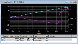
I made the MC calculation based upon 300uV spec 5cm/sec but upon further reflection, and looking at a table in Doug Self's "Small Signal" there is a preponderance of MC carts with much lower output.Someone asked about overhead margin. Here are two graphs. I calculate 18.8dB in the high-gain MC mode, and 13.9dB in the MM mode.
My Audio Technica is rated at 300uV @5cm/sec.
I define the overhead margin as that voltage which raises the pre-pre-amplifier's THD+N to 1%
Small update: I have changed product availability with expected shipping date so it's purchasable again
https://modushop.biz/site/index.php?route=product/product&product_id=971
https://modushop.biz/site/index.php?route=product/product&product_id=971
For those wanting to use a 4-conductor XLR cable, I bought a couple of these and am quite satisfied with them. The conductors are suitable, the cable cover is sealed at the ends, and the plugs have a steel barrel. Price was reasonable.


- Home
- Amplifiers
- Pass Labs
- Pearl 3 Burning Amp 2023