Hello Aiello, something like thiswhat exactly do you need; i have c02laser; cnc, 3d printer and much more,
This is of printables, I'd have to check the size .
It looks particularly sturdy if pprinted witht he right materials. Could possibly be slimmer.
Pete
Hello,
If you are going to have a 3D printed object than you mIght as well not have an L shape but a T shape so you attach it with 4 bolts instead of 2. If you have some skills the mounting holes could be round instead of oval which give a more solid construction.
If you make the big flat area A reasonable thickness you could make some threaded M4 holes on three sides which will allow you to add some new parts( screening material for instance) . Once there are several boards connected it will difficult to add holes especially if they need to be exactly positioned.
Greetings Eduard
which parts do you want to install?Hello Aiello, something like this
View attachment 1260439
This is of printables, I'd have to check the size .
It looks particularly sturdy if pprinted witht he right materials. Could possibly be slimmer.
Pete
Anything that takes my fancy, really. The plastic makes it easy to drill different holes. If there's a bit of thickness I could even tap them. Right now It would be a StationPi, two of Ian's linear power supplies, and a TransportPi digi. I haven't decided where to go next. Probably a more run of the mill power supply for the Pi itself.
I could even use it as a 'foot' for the Waveshare touchscreen.
I like the 'feet' being on one side because then at least one side will always be flat. It may allow for better positioning.
Pete
I could even use it as a 'foot' for the Waveshare touchscreen.
I like the 'feet' being on one side because then at least one side will always be flat. It may allow for better positioning.
Pete
Hello,
Could be a nice opportunity to give this bracket some vibration dampening properties. You could make the flat part with some kind of cavity that can be filled with lead shot, sand through a threaded hole and then closed with a bolt m10. I used this technique for a tubular rack. Yes you need a rather big hole to fill it up.
You could give it two feet on one side and one foot on the centre on the other side. OR use two bigger feet with each two mountings holes.
Not every plastic is good for making a threaded hole. I have used pom material for my diy turntable but i had professional tools at my disposal.Typical stand off for boards is usually m3 which is not easy to make for an average amateur.
Can you print a threaded M3 hole?
Don't forget that special attention should be spend on keeping clocks from falling out off their sockets after you did use several different ones.
Greetings Eduard
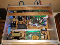
Almost done.
All that remains is to spray the front plate in clear lacquer and create a USB output at the rear.
All that remains is to spray the front plate in clear lacquer and create a USB output at the rear.

Hello everyone,
I was choosing power transformers for my DAC/streamer build, when I bumped into a statement that just confused me so much.
Briefly, 4x9V AC rails needed in total, my plan is to use 2 transformers, each one 2x9V AC with independent coils. I know that one purpose of a multiple-output-coil transformer is powering independent circuits indeed, otherwise center-tap are used.
Gone for the Triad Magnetics VPM18-2780, but then I read this on the datasheet:
"Primary and secondary windings are designed to be connected in series or parallel. Windings are not intended to be used independently"
I'm confused, windings are independent, as datasheet itself clearly reports. Can't I really use them to power 2 different supplies, or is it just some sort of legal/safety/whatever disclaimer by the productor?
If every ac rail needed a transformer, we would see builds with 8-9 transformers or so. I don't think that's the case.
How do you manage your ac supply section?
Thanks
I think what they are taking about is that each transformer has independent secondaries, but they want you to use both of the secondaries in a series or parallel (like you are planning). They don't want you to only use one of the two secondaries on the transformer since that could cause the transformers to overheat.
I suspect that the secundairy windings are not to be used with different / asymmetric load.
Depending on the way the windings are done loading winding 1 with high current en winding 2 with low current will influency the internal magnetic field in a way that it might cause unwanted offset and maybe influence both secundairies ?
Depending on the way the windings are done loading winding 1 with high current en winding 2 with low current will influency the internal magnetic field in a way that it might cause unwanted offset and maybe influence both secundairies ?
Good to hear this attitude 👍 We all tend to comfort our minds / decisions / choices with some confirmation biases, but just the awareness about it is the first and most important step to overcome it. And why is even important in this thread?Confirmation bias is indeed a very human trait, and I'm far from immune to it! 😉
The thing is, I've been following this thread for quite some time, a lurker mostly, and I recently sold a DAC that was over 10 years old and cost around 12K at the time. I believe I can achieve better results, and everyone I know who runs preamps and DACs off the grid has never looked back.
On paper, these UC-Pure MKiii PSUs offer an order of magnitude improvement over the likes of Paul Hynes or Sean Jacobs. So, I took the plunge, and I'm determined to be as meticulous as possible, seeking out all the minute details to ensure the best sound quality.
If anyone has any remorse or regrets and has suggestions for building the ultimate version of Ian's platform, please don't hesitate to drop me a line. Better learn from others mistakes than making them myself, I'll do plenty anyway!
Take this for example - if I state that according to my thorough experimentations, I consider the resonance management of all devices (including digital like switches & routers) a second most important discipline (right after the power supply) - now what will happen in the minds of the most people? I expect that 70-80% will pass it as some unimportand / unbased rant, party because they themselves didn't pay attention to it yet (I was one of them not so long ago, so I still remember how I perceived such statements).
The rest (probably just a minority) already know it or are curious and open-minded enough to at least consider to take a deeper look at it, although still find it hard to believe. My best explanation for this is that we're inherently wired to take seriously only things that we can rationalize according to our personal understanding. But what if our understanding is in fact just extremely limited? While I was experimenting with various materials, tweaks and approaches, I realized that I have to stop making any preconceptions / assumptions and expectations, because almost every one of them turned to be hilariously wrong 😆 On the other hand, my greatest discoveries were made either accidentally or when I expected absolutely nothing.
What I would humbly suggest to everyone is that when you feel you have already decently solved the power supply department, then instead of taking it to extreme, rather shift some attention to other areas, because there are always other gains to be had elsewhere (and most often also cheaper).
My personal shortlist of priorities and rough estimation of their weight to the overall system performance:
22% Power supply / filtering and delivery
18% Vibration/resonance management
15% Noise reduction tweaks / grounding
13% Cabling (ethernet, digital & analog IC, DC and overall cable management)
12% Contacts cleanness/conditioning & other important tweaks
10% Ethernet and Wifi network architecture design & optimizations
10% OS / kernel & software tweaking of endpoint and server
Hello,I am using fifopi q3 with RPI on station pi. 5v PSU are shared with RPI and q3.
If I separate 2x5v, how much current consumption on fifopi side?
If I separate 2x5v, how much current consumption on fifopi side?
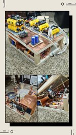
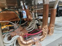
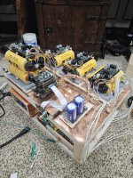
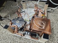
My Best Effort As The Do-Everything-A-Little-Right Ian Canada Build
This is so far, the whole build will be moved and live in a custom grainte case I am having made for me. This weighs 80lbs as is, without the added grainte
1.Everything is grounded. Like everything. Every Positive lead has copper foil added to it with a ground wire to ground bus bar, then added PVC tape or PTFE tape depending on importance of that lead (leads to UCpure do not need PTFE for example)
2. Star ground internal system, which is best, then to a dedicated home audio grounding system.
3. Every wire, every pin, every contact, every piece of everything that is connected, and I mean everything, was treated with deoxit red multiple times using a dremel, then deoxit gold if it was a gold contact or pin, then deoxit blue for shield. I got every single connector as shinny as jewerly. Every UCpure screw even. If it touches a wire or a contact in any way, shape, or form, it was treated.
4. Everything has its own dedicated copper plated enclosure (Pics show rpi in its own, the top all has their own as well, however not pictured here). Everyone is grounded with their own home run to the internal copper bus bar (that was also treated with deoxit) to create a true star ground. You dont want to share grounds until the end. It makes a difference.
5. Everything is on their own layer of sorbothane for vibration
6. Every copper tube is on sorbothate. The Toroidy transformer is on its own sorbothate. Sorbothane everywhere, everything can transmit vibrations, any wire in our out of anything. The IEC is on sorbothane for inlet AC power cord vibrations!
7. There is sorbothane between top and bottom rack, without any screw for physical connection (would transfer vibrations)
8. Every wire is run thru copper grounded tubing, wires that are not are ground wires
9. Extra white wires are for all the top grounding enclosures and wires (not pictured)
10. Inlet IEC is pure copper and treated with deoxit
11. Inlet cabling is 12 guage solid core pure copper, in aluminum conduit, grounded, further shielded with copper thats grounded
12. All wire for power supplies and supplies to Ian parts is pure copper, sold core, 14 gauge, in PTFE, wrapped with additional copper foil layer thats grounded, with final layer of skived PTFE tape (skived is the real deal PTFE)
13. 0.5" very heavy aluminum panels are used between top and bottom layer, they are epoxyed into the top layer. There is then individual bottom copper plates, which are all grounded, on the top.
14- SC-Pure clock pins treated with deoxit red, yellow, blue with dremel shinny as can be. Held secure with tack around the base of the clocks for snug fit and then added sorbothane layer ontop of the clocks. I even dexoit treated the little master clock cable, lol.
14. The entire 80lb frame as pictured sits on 3 5" in diameter 1" sorbothane doughnuts for final build to rack isolation.
(I need to still copper cover and ground the monitor pi pro...temporary location in pics)
I measured almost ZERO EMI or RF, no matter where you measure around the gear, top, bottom, near any wire, any item, the pi, the dac stack, ect. My EMF, even using the Toroidy power supply (dedicated electrical shields between each output that are grounded individually, added EMF shielding, in epoxy, and then stainless steel enclosure for EMF I can measure 300-400 on my EMF meter. Now, directly above it (measure highest EMF directly above a toroidal) with the aluminum and copper, I measure down to 10 or so. This drops off to 2-3 once you move very slightly from dead center above.
If I disconnect the ground from the copper bus bar (out with 16 cable OCC braided cable to Gr research Tube connector) to the audio dedicated ground system I can measure 300-400 for EMI and RF all over the board. Even when the Ucpure is in "pure" mode the AC lines without the above grounding steps are measured in the 200's. Connect the ground back...boom almost 0 everywhere.
I think I thought of everything you can. I run audiolinux on my rpi5 and thats a whole talk in itself as how much my audiolinux server and audiolinux pi are tweaked to perfection. My networking is all home clocked on GPSDO OCXO and I made every xlr and cable, with OCC copper braids, added foil, ptfe layers, and repeated multiple times, each layer with their own dedicated grounds. I use a Lush^3 USB cable which is killer for Pi to DDDC which I can lift grounds, one side ground, both, connect shields in parallel, series, ect
I dont think I can really think of what else I can do. It will look very nice and high end once its in my custom CNC granite case.
I thought about added shielding between layers of all the Ian parts, but I dont think it is needed here. I cant measure any EMI or RF around or between any of the boards. This is likely due to everything being grounded already and noise from the stack goes out via its grounding.
I spent a LOT of time laying out this build, thinking of everything, measuring, moving things, testing testing testing. I can tell you all of this work IS WORTH IT and the sound compared to my video showing the test build is VERY REAL and this thing sounds WOWOWOWOW....without any wire burn in either.
PS - Don't mind the mess and random HDMI cable that normally is not there, I just was excited to get it playing again after 3 weeks of many many many hours spent getting from test bench build to this.
Attachments
Last edited:
@badd99
Thanks for sharing. Your build is badd ***!
I took a similar route in 2013 when I laid out my streamer DAC but it pales in comparison to your efforts. I wanted to keep all the noisy stuff at one side, in its own copper clad case, dampened and away from sensitive stuff. It was an epiphany when I realized this could be 3d.
I appreciate your use of grounded copper pipe. Also the big copper bus bar. I found star grounds and a massive copper ground buss to work well.
I love the use of granite for the outer chassis. I used solid walnut. If I did this again, I'd replace all the walnut with granite in my streamer, monoblocs and open baffle speakers. That will never happen but I can appreciate what you have done. Hope it sounds as good as I imagine it will.
Congratulations.

Just purchased the parts for this and also have the Gustard r26 DAC. Are there any issues connecting the streamer to the DAC? What IS2 cable works between the HDMI Pi Pro and the Gustard R26? I am using Roon with Ropiee software on the Raspberry Pi. Does anyone know the right settings in Ropiee to make the connection?Hello all - hope everyone is well.
I have, following much input from Ian Canada and inspiration from Gabster managed to put together the following stack:
This combination has comprehensively outperformed both the PIAES2 streamer / DDC and the internal streamer in the Gustard R26 DAC. I am very pleased with the improvement in sound quality that Ian's components have enabled in my system with the R26 as the DAC.
- PurePi II
- RPi 4
- FiFoPi Q7
- HDMI Pi Pro
- UcConditioner 3.3v
Attention now inevitably turns to the next incremental improvement and I have a few questions for @iancanada, if I may please:
Many thanks in advance
- On the topic of isolation of the RPi to improve sound quality, and building on your post #10,702, then:
- Would the IsolatorPi yield sonic benefits in my stack?
- How would I incorporate the IsolatorPi into my stack above in terms of Power.
- What is the status of the SC-Pure clocks for the 90/98 frequencies, please? When do you think these might be available to order? Ideally, I would like to order these in the current group buy.
SA
Thanks for your help.
Man! Congratulations! What a build! 😜My Best Effort As The Do-Everything-A-Little-Right Ian Canada Build
This is so far, the whole build will be moved and live in a custom grainte case I am having made for me. This weighs 80lbs as is, without the added grainte
1.Everything is grounded. Like everything. Every Positive lead has copper foil added to it with a ground wire to ground bus bar, then added PVC tape or PTFE tape depending on importance of that lead (leads to UCpure do not need PTFE for example)
2. Star ground internal system, which is best, then to a dedicated home audio grounding system.
3. Every wire, every pin, every contact, every piece of everything that is connected, and I mean everything, was treated with deoxit red multiple times using a dremel, then deoxit gold if it was a gold contact or pin, then deoxit blue for shield. I got every single connector as shinny as jewerly. Every UCpure screw even. If it touches a wire or a contact in any way, shape, or form, it was treated.
4. Everything has its own dedicated copper plated enclosure (Pics show rpi in its own, the top all has their own as well, however not pictured here). Everyone is grounded with their own home run to the internal copper bus bar (that was also treated with deoxit) to create a true star ground. You dont want to share grounds until the end. It makes a difference.
5. Everything is on their own layer of sorbothane for vibration
6. Every copper tube is on sorbothate. The Toroidy transformer is on its own sorbothate. Sorbothane everywhere, everything can transmit vibrations, any wire in our out of anything. The IEC is on sorbothane for inlet AC power cord vibrations!
7. There is sorbothane between top and bottom rack, without any screw for physical connection (would transfer vibrations)
8. Every wire is run thru copper grounded tubing, wires that are not are ground wires
9. Extra white wires are for all the top grounding enclosures and wires (not pictured)
10. Inlet IEC is pure copper and treated with deoxit
11. Inlet cabling is 12 guage solid core pure copper, in aluminum conduit, grounded, further shielded with copper thats grounded
12. All wire for power supplies and supplies to Ian parts is pure copper, sold core, 14 gauge, in PTFE, wrapped with additional copper foil layer thats grounded, with final layer of skived PTFE tape (skived is the real deal PTFE)
13. 0.5" very heavy aluminum panels are used between top and bottom layer, they are epoxyed into the top layer. There is then individual bottom copper plates, which are all grounded, on the top.
14- SC-Pure clock pins treated with deoxit red, yellow, blue with dremel shinny as can be. Held secure with tack around the base of the clocks for snug fit and then added sorbothane layer ontop of the clocks. I even dexoit treated the little master clock cable, lol.
14. The entire 80lb frame as pictured sits on 3 5" in diameter 1" sorbothane doughnuts for final build to rack isolation.
(I need to still copper cover and ground the monitor pi pro...temporary location in pics)
I measured almost ZERO EMI or RF, no matter where you measure around the gear, top, bottom, near any wire, any item, the pi, the dac stack, ect. My EMF, even using the Toroidy power supply (dedicated electrical shields between each output that are grounded individually, added EMF shielding, in epoxy, and then stainless steel enclosure for EMF I can measure 300-400 on my EMF meter. Now, directly above it (measure highest EMF directly above a toroidal) with the aluminum and copper, I measure down to 10 or so. This drops off to 2-3 once you move very slightly from dead center above.
If I disconnect the ground from the copper bus bar (out with 16 cable OCC braided cable to Gr research Tube connector) to the audio dedicated ground system I can measure 300-400 for EMI and RF all over the board. Even when the Ucpure is in "pure" mode the AC lines without the above grounding steps are measured in the 200's. Connect the ground back...boom almost 0 everywhere.
I think I thought of everything you can. I run audiolinux on my rpi5 and thats a whole talk in itself as how much my audiolinux server and audiolinux pi are tweaked to perfection. My networking is all home clocked on GPSDO OCXO and I made every xlr and cable, with OCC copper braids, added foil, ptfe layers, and repeated multiple times, each layer with their own dedicated grounds. I use a Lush^3 USB cable which is killer for Pi to DDDC which I can lift grounds, one side ground, both, connect shields in parallel, series, ect
I dont think I can really think of what else I can do. It will look very nice and high end once its in my custom CNC granite case.
I thought about added shielding between layers of all the Ian parts, but I dont think it is needed here. I cant measure any EMI or RF around or between any of the boards. This is likely due to everything being grounded already and noise from the stack goes out via its grounding.
I spent a LOT of time laying out this build, thinking of everything, measuring, moving things, testing testing testing. I can tell you all of this work IS WORTH IT and the sound compared to my video showing the test build is VERY REAL and this thing sounds WOWOWOWOW....without any wire burn in either.
PS - Don't mind the mess and random HDMI cable that normally is not there, I just was excited to get it playing again after 3 weeks of many many many hours spent getting from test bench build to this.
The copper piping serves as a brilliant and simple yet efficient Faraday shield. Your work on it is very impressive. Please keep us updated on how it affects the sound. Given your highly resolving system, I'm eager to hear your thoughts and impressions.
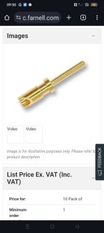
I have a question about the green connectors. All the screws are iron-ish or magnetic in some way. I was thinking about changing them to copper screws too. Have you already made this change? I began the process of replacing the entire connectors with PTFE ones, but it's quite tedious with all the desoldering, cleaning, and resoldering involved. Just changing the contact screws should suffice. lots of people such as Dany Ritchie or the guys at Purifi seems to avoid iron like the plague in all their builds. I respect their expertise, so I'll follow suit rather than experimenting unnecessarily.
I'm also making some changes to the Vishay Dale resistors on the OPA861 by replacing them with AN tantalum ones. It only requires four, so it's a relatively easy modification that could yield interesting results.
Lastly, If you don't mind, I might also borrow your copper pipe idea. 😉 👊🏼
Hello,
I know that in the DDDAC there have written several pages about changing the resistors at the output. But i think the DDDAC is in a different class!
But upgrading the resistors with a bit more " sound quality" could be worthwhile.
I use nothing but AN in my phonostage but they are expensive. Maybe better wait for the DDDAC mk3.
Why not skip the connector completely and use these from Bulgin. They are goldplated copper are solder the wire directly onto the board if you want disassemble it every year.
Greetings Eduard
Attachments
And now for another perspective on resistors. I tried many different resistors for I/V on output. The original AN tantalum were among the worst to my ear. After many experiments I found hand rolled manganin wire to be the absolute best. I don't know what the function is for these resistors. Perhaps AN will work for you in this application. But if they do not, consider manganin when passing an audio signal.
There is no common I2S standard for the HDMI connector pin assignments. PS Audio is the most widely used, Gustard has their own and there are at least a handful more. Maybe a month or two ago Ian posted here about his new HDMIPi Pro II which should be able to get over the hurdles of this unstandardized field. I remember Ian posting about his successful tests with several different non-PSAudio DACs including R26. However HDMIPi Pro II documentation has not been posted to Github yet.Just purchased the parts for this and also have the Gustard r26 DAC. Are there any issues connecting the streamer to the DAC? What IS2 cable works between the HDMI Pi Pro and the Gustard R26? I am using Roon with Ropiee software on the Raspberry Pi. Does anyone know the right settings in Ropiee to make the connection?
Thanks for your help.
With my GB order I have ordered also HDMIPi Pro II as I also have the R26 but my package is still in customs, I hope to get it out of customs during this week and then I would be able to test whether this combo will actually work.
- Home
- Source & Line
- Digital Line Level
- Asynchronous I2S FIFO project, an ultimate weapon to fight the jitter