David, sorry, I don't intend to sidetrack, is HR limited to 4 segments? I might have missed that

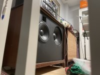
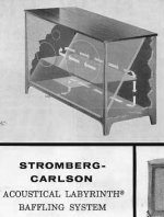
I have a pair of Stromberg Carlson "bass labyrinth" speakers that are a cross between a rear folded horn and a rear TL speaker. I'd like to model them and after running through Hornresp today I think it could do it, however it is folded but not flared like a horn - consists of a triangular chamber behind the front baffle that feeds into a rear triangular chamber that then feeds to a lower chamber that then feeds to a bottom-firing port. It might be "pseudo" flared in the sense that the rear chamber is larger than the front. The bottom-firing port then feeds to legs that I believe serve as the final port. I'm going a little bit by memory but I do have SolidWorks files on it. I think Hornresp could model it though maybe a simpler route would be treating it like a bass reflex and tuning the bottom firing port. I will be checking the impedance of the bass driver to see where I am relative to fc of the woofer
These were prototypes from the Stromberg Carlson factory acquired by way of my father ca. 1950-1955. They may be 10 years older than that because he bought them from a colleague who had a low WAF for them which may have lasted ten years. I rebuilt the front speakerboard using basic math on wavelength and port size about ten years ago and revised the tweeter/mid. But I'd like to develop a more detailed model. Original drivers were Altec Lansings which my dad replaced with Universities and an engineer he worked with (at Sylvania) redesigned a crossover and put a dome tweeter with a JBL midrange. I replaced all of them with a horn, sealed midrange, and woofer that closely matched the TS parameters of the Universities as a starting point. It looks like the triangular internals may have served as some sort of horn stub originally (was told these were prototypes originally) that were then converted to the reflex.
Should this be modeled as a horn with a quantized approximation (stepped along a horn formula), or several waveguides, or several transmission lines?
Attachments
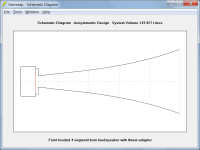
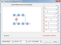
It's been a minute since I've got to use the latest version of HR on my home laptop. Is there a 5th segment for TH's yet?Four segments is normally the limit however a front loaded horn can have in effect five segments by specifying a throat adaptor as shown in Attachment 1, and Paraflex horns have seven segments as shown in Attachment 2.
Should this be modeled as a horn with a quantized approximation (stepped along a horn formula), or several waveguides, or several transmission lines?
It's an unfilled offset driver pipe. Perhaps start a thread elsewhere--this is David's thread for his software.
Attachments
Is there a 5th segment for TH's yet?
In a word, NO, and it's not going to happen - ever 🙂.
I'm still trying guy...LOL!
I can see that - it makes you very trying indeed 🙂
(Not really, just kidding - couldn't resist it)
Improved Hornresp Security
Hi Everyone,
The Hornresp server site now uses HTTPS (Hypertext Transfer Protocol Secure) encryption for improved security:
https://www.hardware-test.de/mcbean/Setup.exe
The link on the http://www.hornresp.net Hornresp download web page has been amended accordingly.
The post linked below, and subsequent posts in the same thread refer:
https://www.diyaudio.com/community/threads/would-this-shape-work.407462/#post-7559312
Kind regards,
David
The Hornresp server site now uses HTTPS (Hypertext Transfer Protocol Secure) encryption for improved security
Many thanks to Sabbelbacke for making the above possible!
Hi David,
would the attached record be a good way to simulate the low end part of a MEH where the wofers are running open backed? I used offset compound horn with a very short second horn and the pathlength calculated from the center of the entry port to the center of the back of the woofer.
would the attached record be a good way to simulate the low end part of a MEH where the wofers are running open backed? I used offset compound horn with a very short second horn and the pathlength calculated from the center of the entry port to the center of the back of the woofer.
Attachments
Hi pelanj,
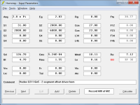
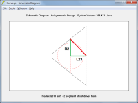
If you are comfortable in analysing just the low frequency part of the multiple entry horn in isolation, rather than considering the complete system, then possibly the simplest way to do it would be to use the attached OD model. The 34.1 cm path length shown by the red line on the attached schematic diagram was calculated as follows:
R2 = (S2 / Pi) ^ 0.5 = (2000 / Pi) ^ 0.5 = 25.23
Path = (R2 ^ 2 + L23 ^ 2) ^ 0.5 = (25.23 ^ 2 + 23 ^ 2) ^ 0.5 = 34.14 cm
The Path length is the straight line distance between the centres of the two point source outputs.
It may also be worth allowing for an offset driver throat chamber and throat chamber port volume between the LF drivers and the horn.
Kind regards,
David
Attachments
Hornresp Update 5530-240114
Hi Everyone,
BUG FIX
If a Ripole record was exported from Version 54.00 and imported into the Version 55.30 update released on 7 January, OD2 would not automatically change to OD3.
This bug has now been fixed.
Kind regards,
David
Hi Everyone,
BUG FIX
If a Ripole record was exported from Version 54.00 and imported into the Version 55.30 update released on 7 January, OD2 would not automatically change to OD3.
This bug has now been fixed.
Kind regards,
David
I finally ran the simulation and I do not fully understand the path length - I understand how you define it, but I thought the outer wall of the horn would form a "baffle" - so I would add R3 to the red line intuitively - to calculate the path around the horn wall to the center of the mouth. I might even try to add a ring between the woofers and the mouth to increase the distance a bit?The Path length is the straight line distance between the centres of the two point source outputs.
I do not fully understand the path length
Hopefully the two posts linked below and the PDF document and additional posts that they in turn link to, will make things a little clearer.
https://www.diyaudio.com/community/threads/hornresp.119854/page-427#post-5500906
https://www.diyaudio.com/community/threads/hornresp.119854/page-523#post-6069923
Thank you, I think I am getting it now. Hornresp simulates two point sources separated in space. That means that the real life situation will be different due to the sources not being point sources. Is there any way to set the path length in the MEH wizard or is it calculated automatically from the horn parameters? Or is it set to zero?
Is there any way to set the path length in the MEH wizard or is it calculated automatically from the horn parameters? Or is it set to zero?
In a two-way multiple entry horn system, if the ME1 driver assembly does not have a sealed rear chamber then a Path length can be specified by the User.
In a three-way multiple entry horn system, if the ME2 driver assembly does not have a sealed rear chamber then a Path length can be specified by the User. The ME1 driver assembly must have a sealed rear chamber.
The default Path length in each case is zero centimetres.
Attachments

- Home
- Loudspeakers
- Subwoofers
- Hornresp