None
It's a Parabolic horn. Your entire Box has two parallel walls.
Interpretation is key.

It's only parabolic if the two other walls expand linearly all the way. It is possible to have a conical or exponential horn with two parallel walls.
Are you serious? You are fooling me!
It's a tapered, with offset, Transmission Line.
A lot similar to a PMC FB1 (actually the first prototype was designed and built 18 years ago, independently by me, using the MJK worksheets).
Please go to PMC and say that a FB1 is a Parabolic Horn. I can hear them already laughing.
https://positive-feedback.com/Issue48/pmc_fb1.htm
It's a tapered, with offset, Transmission Line.
Yes, but still parabolic horn, parabolic is about the flare not the box definition or name. 🙂
I give up. I know that the next "expert" will call it tesseract horn.
Look at the box volume (in schematic) between a variety of flare rates (par, con,exp) in a really long horn or tapered Qw pipe and you’ll see the ‘shape’ has affected the ‘math’ that too hard to explain in words ?Are you serious? You are fooling me!
It's a tapered, with offset, Transmission Line.
A lot similar to a PMC FB1 (actually the first prototype was designed and built 18 years ago, independently by me, using the MJK worksheets).
Please go to PMC and say that a FB1 is a Parabolic Horn. I can hear them already laughing.
https://positive-feedback.com/Issue48/pmc_fb1.htm
View attachment 1255046
Last edited:
FWIW, I wasn't commenting on your design, only that the type of flare is not necessarily parabolic just because two walls are parallel.No hope.
If the speaker is a horn or transmission line is really beside point, that's not what we are actually discussing here. But that people starting using the word "horn" when describing the type of flare of the transmission line may be the reason you think we are all stupid for calling your transmission line a horn 😆
Read the above posts again, but substitute "flare" for "horn" and it may make a little more sense...
It's a parabolic expansion (or contraction, depending on which end you start with).
But it's not a horn. Very few bass horns are actually horns in any case. They're more 1/4 wave resonators. A true bass horn would be huge. HUGE.
So I'd call it a 1/4 wave resonator with a parabolic path profile. The 1/4 wave resonators with low or negative expansion rate are commonly referred to as transmission lines.
Brian Steele, thanks! Finally!
Notice that I started asking about Directivity Index and people gave to a design that is commonly referred as transmission lines all the possible fancy names.
This is something I never asked for.
If you really want to use the term "parabolic" you could argue about the approximation made by me (and MJK too) of a duct having rectangular sections with a duct having circular sections.
Oh! but this is hard Mathematics and not "common sense".
Where's the Directivity Index question?
Note, I didn't say HORN.
I used the HORN pics to show the 3 different expansion/contraction types.

Note, I didn't say HORN.
I used the HORN pics to show the 3 different expansion/contraction types.
I want to reproduce the Directivity Index.
I have seen it in HornResp but in the cylindrical example I'm using the menu entry is disabled.
If you are referring to the design you show in Post #14,102 then simply replace the four segments with the following single equivalent one, and the Directivity tools will be enabled.
S1 = 204 cm^2
S2 = 204 cm^2
L12 (Con) = 176.40 cm
Where's the Directivity Index question?
#14,098, My first question. I hope that you understand that asking about how to relate PWL to SPL is asking about the Directivity Index.
#14,101, David McBean shows a formula relating PWL and SPL and using explicitly Directivity Index.
#14,117, and so on ...
All the rest is in your fantasy.
In YOUR post #14102, YOU posted a MODEL of a CON enclosure and then posted a BUILD of a PAR enclosure in post #14121. How's that for fantasy.
I did it only because I was asked to do so. Please! Stop from drinking alcohol in the morning. And read the post of Brian Steele.
I don't care at all to know that my line is a catenoid horn. I'm only interested to know how to relate PWL and SPL.
I don't care at all to know that my line is a catenoid horn. I'm only interested to know how to relate PWL and SPL.
Stop from drinking alcohol in the morning
It's public forum, try to be more polite and fun, maybe what you are interested is not what people are interested, so you need to leave with that.
The only time that the User will now be required to manually change OD2 to OD3 is when a Ripole record exported from an older version of Hornresp is imported into the proposed new version.
The above OD2 to OD3 conversion process will now also happen automatically.
Hornresp Update 5530-240107
Hi Everyone,
CHANGE 1
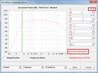
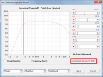
The 4th Order Butterworth alignment option shown in the bass reflex loudspeaker wizard actually calculates results for a 4th Order Boom Box. The option name has been corrected (see Attachment 1) and a separate new option has been added for the 4th Order Butterworth alignment (see Attachment 2). The Help file has been amended accordingly.
Available bass reflex alignment options are now:
Default Alignment
4th Order Butterworth
4th Order Boom Box
3rd Order Quasi-Butterworth
4th Order Chebyshev
A characteristic of the 4th Order Butterworth alignment is that the Helmholtz resonance frequency fb is theoretically equal to the driver resonance frequency fs (see Attachments 2 and 3). In practice however, depending upon whether the chamber resonances 'masked' or 'not masked' option is selected, and because of slight differences introduced by calculating driver Thiele-Small parameter values from their electro-mechanical equivalents, Hornresp may sometimes show a discrepancy of 0.1 Hz between fb and fs.
CHANGE 2
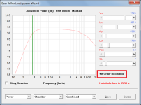
If an alteration is made to a system dimension after a closed box alignment, bass reflex alignment or transmission line method has been specified in the loudspeaker design wizard, the colour of the alignment or method label changes from black to grey to indicate that the standard alignment or method shown no longer strictly applies (see Attachment 4).
Double-clicking on the grey label resets the sliders to the standard alignment values.
CHANGE 3
The Ripole loudspeaker configuration code has been changed from OD2 to OD3. Existing Ripole records will automatically update to OD3.
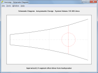
The OD2 configuration code now applies to a four-segment offset driver horn with the driver entry point at S4 (see Attachment 5).
NOTE - As previously foreshadowed, the addition of the new OD2 configuration has required a considerable amount of work and the chance of something having been missed is reasonably high. Could you please report any bugs found.
Kind regards,
David
Hi Everyone,
CHANGE 1
The 4th Order Butterworth alignment option shown in the bass reflex loudspeaker wizard actually calculates results for a 4th Order Boom Box. The option name has been corrected (see Attachment 1) and a separate new option has been added for the 4th Order Butterworth alignment (see Attachment 2). The Help file has been amended accordingly.
Available bass reflex alignment options are now:
Default Alignment
4th Order Butterworth
4th Order Boom Box
3rd Order Quasi-Butterworth
4th Order Chebyshev
A characteristic of the 4th Order Butterworth alignment is that the Helmholtz resonance frequency fb is theoretically equal to the driver resonance frequency fs (see Attachments 2 and 3). In practice however, depending upon whether the chamber resonances 'masked' or 'not masked' option is selected, and because of slight differences introduced by calculating driver Thiele-Small parameter values from their electro-mechanical equivalents, Hornresp may sometimes show a discrepancy of 0.1 Hz between fb and fs.
CHANGE 2
If an alteration is made to a system dimension after a closed box alignment, bass reflex alignment or transmission line method has been specified in the loudspeaker design wizard, the colour of the alignment or method label changes from black to grey to indicate that the standard alignment or method shown no longer strictly applies (see Attachment 4).
Double-clicking on the grey label resets the sliders to the standard alignment values.
CHANGE 3
The Ripole loudspeaker configuration code has been changed from OD2 to OD3. Existing Ripole records will automatically update to OD3.
The OD2 configuration code now applies to a four-segment offset driver horn with the driver entry point at S4 (see Attachment 5).
NOTE - As previously foreshadowed, the addition of the new OD2 configuration has required a considerable amount of work and the chance of something having been missed is reasonably high. Could you please report any bugs found.
Kind regards,
David
Attachments

- Home
- Loudspeakers
- Subwoofers
- Hornresp