I take a negative impression of this tester.
You can see the voltage of the 9V battery go down with subsequent measurements.
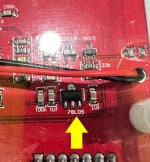
Flip over the Mega328 and look at the bottom of the PCB. You'll see that it includes a 5.0V regulator IC which converts the time-varying battery voltage, to a constant, unvarying, regulated 5.0 volts.
_
Attachments

That's a good approach. Makes measuring current draw easier too!solder them with longer legs and just beside of the holes
Ok, and then solder it into the holes if it "fits" from the top is my plan........with trimmed legs of course.

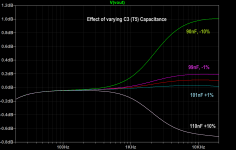
Here's a graph of various values of the T5 (75us) capacitor, C3 and the effect of compliance to the RIAA curve.
This goes along with my experience assembling the Hagerman Bugle kit.
Thanks DT
@Zen Mod
you could use your extra, fancy 47-step attenuator with hand-matched precision RN55 metal films.
(yes, I was joking)
With remote control....
Doesn't the Xono have remote control?
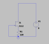
It is not possible to predict just measuring the Idss using my Peak DCA75 tester?@MEPER : You can try a circuit like the attached and adjust R1 to get the current near what you want before solder the parts in place.
Then I could maybe find another J112 that has "correct" Idss?
It is not possible to predict just measuring the Idss using my Peak DCA75 tester?
Then I could maybe find another J112 that has "correct" Idss?
My approach is to measure the voltage in the circuit then use that voltage to find a pair of matching IDSS J112 jfets one for each left and right then select a pair of matching source resistors to provide the specified current.
Then after measuring and selecting the parts solder it all together.
That way both channels will be the same.
Thanks DT
It could be nice to have exact bias match on both channels.
I know I have a bag of 1000 pcs. J113 but those have probably too high Idss.
I know I have a bag of 1000 pcs. J113 but those have probably too high Idss.
My memory was wrong J113 has the lowest Idss according to data sheet but they spread a lot so maybe possible to find a pair that can be used.
But probably better to get a bag of J112 to select from to get at nice pair as other parameters differs like RDS(On).
But probably better to get a bag of J112 to select from to get at nice pair as other parameters differs like RDS(On).
A bag of J112's would work out nice. J113's would work. I also have a tea cup full of PF5102's.
Thanks DT
Attachments
No remotes on the Phono stages.With remote control....
Doesn't the Xono have remote control?
^
Aah, I was refererring to the DIY versions.
https://www.diyaudio.com/community/threads/new-build-pass-xono-2019-rstaudio.395214/ See Randy's, post #13.
Aah, I was refererring to the DIY versions.
https://www.diyaudio.com/community/threads/new-build-pass-xono-2019-rstaudio.395214/ See Randy's, post #13.
I received the P3 kit and I did a measurement on the two J112 in the package using the DCA75. They are relative close to each other. I think close enough.
The DCA75 reads out these parameters:
Vgs_off: -3.84V, -3.63V
Vgs_on: -2.85V, -2.65V
gfs: 9.1mA/V, 8.8mA/V
Idss: 12.0mA, 12.0mA
Rds_on: 27.7 ohm, 28.0 ohm
I will probably do the measurement Dennis Hui suggested and if inside the bias interval I think I am good to go with these two J112.
The J112 is not operated at Vgs = 0 in P3 circuit but Vgs will be a bit negative. Then bias current will be less than 12mA......but I am not able to calculate in my head what the result will be "in-circuit".
Started stuffing the board. Very well made kit. Looking forward to listening to it soon.
Must thank you for the suggestion of the lead bender. I can't believe I have been building electronic kits since the 70's and never used one.
Thanks
Debra
Must thank you for the suggestion of the lead bender. I can't believe I have been building electronic kits since the 70's and never used one.
Thanks
Debra
- Home
- Amplifiers
- Pass Labs
- Pearl 3 Burning Amp 2023