Not if accurate.Ok, I'm going to give you a rundown on the nature of a vacuum tube. This is going to open up another can btw...
No.A vacuum tube is an electron media crossing transmission line that transmits electrons from its cathode to plate from the 2 dimensional media of a wire to the 3 dimensional space of a vacuum.
No transmission lines inside a triode.
IF you want to use that language, a wire approaches "unidimensional* more than "bidimensional", but in any case it's of little importance here.
Pseudo techno babble.Current flow elements called grids are constructed between the cathode transmission antenna to the receiving plate antenna.
"Antennas"???
Absolutely NOT.
You have NO CLUE about what an Antenna is.
The basic type is piece of conductor (say a wire) , along which a current flows, there is a voltage differential between its ends and it creates a electromagnetic field around.
Another antenna captures that electromagnetic field and turns it back into a voltage differential.
You can also create current through it if you load this voltage.
ABSOLUTELY NONE OF THAT HAPPENS IN A VACUUM TUBE.
How?The electron flow volume and flow rate are controlled by the grid elements.
Please elaborate.
You started with the wrong foot on this.The noise of a vacuum tube is a product of the electrons resisting receiving from the plate back into the 2 dimensional media of wire.
No beam focus in a triode.Observation of the tube noise is on the plate it shows the lack of electron beam focus.
Google "beam tetrode" or "cathode ray tube".
And in any case irrelevant to noise.
No.The electron beam focus is the steady flow of electron coming out of the cathode back into the plate.
Google "focus" definition.
What does "harmonic propagation" mean?In harmonic distortion is the product of the harmonic propagation effect
Irrelevant.of the cathode transmitting into 3 dimensional space
Please elaborate if you think it means something.
PS: "elements called grids" is language I would use to describe tubes to somebody who has absolutely no clue about Electronics.
But we are in "DIY" "Audio".
The admission level here is already higher than that.
Last edited:
You are not answering my question.it has to be an Ayrton–Perry wire wound non inductive resistor. There are several types.
By what physical mechanism does it create noise?
Or less than a same value and size and temperature metal film one?
Hint: "brand" does not explain it.
I have to explain it in a way that others can understand the electron tube propagation model.PS: "elements called grids" is language I would use to describe tubes to somebody who has absolutely no clue about Electronics.
But we are in "DIY" "Audio".
The admission level here is already higher than that.
I apologize if this creates too much of a paradigm shift for you. This model was created before electron theory and a vacuum tube engineer told me this long ago and how he saw the device. Funny how many people now these days pay big bucks for those tubes he engineered long ago for RCA and Amperex.
That type of resistor suppress rf noise. Are you too spurious in the closed mind that you display for this to sink in?By what physical mechanism does it create noise?
A resistor creates noise from all the billiard balls rattling around inside it. The larger the resistance and the higher the temperature, the larger the noise voltage appearing at its terminals caused by the rattling. If no current is passing through it, there are no other noise mechanisms, and all resistors are same-same. No voudou.
All good fortune,
Chris
All good fortune,
Chris

Correct. There is no need to use 'non inductive' resistors. That only matters at RF with values well under 10 ohms.Fat chance.
Unless it's an "experiment" flawed on purpose to."prove" a point.
There is absolutely no physical mechanism by which a cathode metal film resistor should create visibly higher noise than a wirewound one.
The grid stopper resistor's role is to stop possible instabilities leading to distortion, overshoot or auto-oscillations at high level of gain or loudness.
This is a very common feature found on numerous tube guitar amps, but also on Hi-Fi amps.
Values can vary from 1K to 10K, but the 1.5K is probably the most encountered. Below a Fender Twin-Reverb :
View attachment 1245933
T
The resistors (1500 in the schematic) are not simply grid stoppers.
Guitar amps are designed for operation in overload (saturation of the output valves).
At overload (saturation) the grids conduct. The high-value grid resistors are designed to limit the grid current - partly to limit the anode current, and partly to limit the grid current that must also flow in the grid coupling capacitor. Shaping the grid curent in this way as quite an influence on the overload sound - not least because the grid current charges the coupling capacitor, which in turn biases the output valve to lower anode current (aka Blocking Distortion, or in the Guitar world: »Farting Out«). The dynamics of this biasing are configured by the values of the coupling capacitor, the grid couling resistor, and the grid leak resistor.
A similar purpose can be seen in the GEC/Marconi-Osram application notes for audio amplifiers. In many cases these circuits show grid resistors of 10-15kΩ in circuits using RC-coupling; the principal purpose is to limit grid current.
Well we haven't gotten past self bias type yet without all their belly aching. Much less how they play a role as bias limiters, and voltage source points in things like guitar amps.Guitar amps are designed for operation in overload (saturation of the output valves).
At overload (saturation) the grids conduct. The high-value grid resistors are designed to limit the grid current - partly to limit the anode current, and partly to limit the grid current that must also flow in the grid coupling capacitor. Shaping the grid curent in this way as quite an influence on the overload sound - not least because the grid current charges the coupling capacitor, which in turn biases the output valve to lower anode current (aka Blocking Distortion, or in the Guitar world: »Farting Out«). The dynamics of this biasing are configured by the values of the coupling capacitor, the grid couling resistor, and the grid leak resistor.
I find it interesting these kids like tubes and the way we built them, but when you start telling them things, they want you to break out math or 'prove' it.
Guitar amps are designed for operation in overload (saturation of the output valves).
No, sorry : it's the players who used the guitar amps (and others) in overload situation - amps that were not intended nor designed for this. I hear Leo Fender, Ken Bran, Dick Denney, Dave Reeves laughing from their graves... 😆😕
I unfortunately do not retrieve this early 60s ad from Marshall boasting "100W of clean, undistorted tone" from their big amps...
A Fender Twin-Reverb is considered The King of Klean (and at a lesser extent, the Super-Reverb). Remove the 1500 ohms grid stoppers from the output stage and (try to) play it at full volume : it will give an unpleasant fizzy-buzzy sound before entering in oscillation, like many other Fenders.
Pink Floyd favoured the Hiwatts DR103 because of their deep clean tone, while Pete Townshend invariably turn the volume knob to 10 for its killing-windmill-loudness... Here is below the output power measurements that provided a DR103 after servicing :
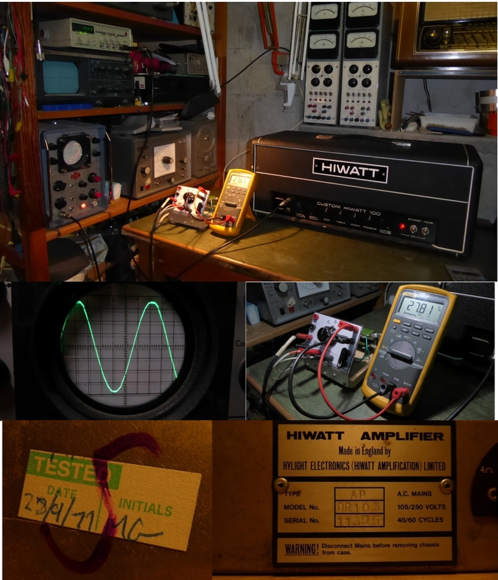
With the supply set on 240V tap while the mains network was circa 230V, the onset of clipping (see oscillogram) is reached at 27.81VRMS @400Hz/8 ohms (see TRMS DMM), that is to say 96.7W RMS clean tone for a 100W amp. Indeed, these amps were not designed for overload operation, but for clean power !
See the output stage of the DR103 below - note the 22K serial grid resistors to avoid instability when played overdriven - or not.
Note : we speak about power stage overload, not the very common preamp gain / master volume features, which came later (think Boogie) and were indeed designed for controllable overload and saturation tones at different degrees, unlike the power stages that were (and are still) incidentally pushed to overdrive by the guitarists...
T
Last edited:
I'm sure you can find some guitar amp that can't be easily overloaded (yes, output stage) but that would be an exception.
And if it can be done, it will.
Do you think the designer didn't notice the possibility ?
The 22k grid resistor in the picture above is 40dB too high in value to be a simple stopper: even 100 ohm is enough for most cases. But it is perfect for a grid current limiter - which is what it is.
And if it can be done, it will.
Do you think the designer didn't notice the possibility ?
The 22k grid resistor in the picture above is 40dB too high in value to be a simple stopper: even 100 ohm is enough for most cases. But it is perfect for a grid current limiter - which is what it is.
Do you think the designer didn't notice the possibility ?
Yes. Tipically Leo Fender and Ed Jahns at Fender. More than this : they did not understand, and even ignored it... That's why they missed the plane, the train and boat of the preamp overdrive concept, as popularized by Randall Smith, the founder of MESA in the mid 70s.
The introduction of the Master Volume in Marshall amps came with the advent of the JCM800 series (2203, 2204...) in the early 80s. This feature was simply ignored before.
T
Last edited:
Not to mention you are not going to overload a negative feedback amplifier. Which most of them are.No, sorry : it's the players who used the guitar amps (and others) in overload situation - amps that were not intended nor designed for this. I hear Leo Fender, Ken Bran, Dick Denney, Dave Reeves laughing from their graves... 😆😕
I missed this mass confession of Design sins.they did not understand, and even ignored it... That's why they missed the plan
Channelling of design intentions, real or imaginary, makes no difference though.
22k ohm of grid resistance is not necessary to suppress oscillation in a power valve. But it is perfectly in the range for grid current limitation.
Earlier in the thread there is a post of J.Miller's evaluation of the likely range of negative grid resistance that appears for certain inductive anode loads. If you believe that 1.5 or 22k ohm is needed to prevent oscillation, perhaps you can use Miller's calculation to show us how.
correct. However, you need to put in a 47K coupling resistor to prevent loading effects in the guitar tone controls.22k ohm of grid resistance is not necessary to suppress oscillation in a power valve. But it is perfectly in the range for grid current limitation.
I missed this mass confession of Design sins.
Channelling of design intentions, real or imaginary, makes no difference though.
22k ohm of grid resistance is not necessary to suppress oscillation in a power valve. But it is perfectly in the range for grid current limitation.
Earlier in the thread there is a post of J.Miller's evaluation of the likely range of negative grid resistance that appears for certain inductive anode loads. If you believe that 1.5 or 22k ohm is needed to prevent oscillation, perhaps you can use Miller's calculation to show us how.
There's no need to calculate anything, just having hundreds amps to service, repair and restore to understand the use of those resistances for fizz and oscillation taming. Remove or minimize the value of those resistor and you will hear what I am speaking about.
Look at this Marshall 18W 1974X (RI). Why do you think the designers puts the resistors R15 and R20 at 8.2K in cathode bias power stage with moderate plate voltage, which à priori would not need them ?
Following the advice of a so-called expert (TAG forum) to remove these resistors in order to increase distortion and harmonics while adding a master volume on the 1974X (a crime !), an owner bring me his modified amp for fizz-oscillation problems... Guess what was the cure ?
The more the Gm (or S) of the tube is high (EL34, EL84 vs. 6L6, 6V6), the more the serial grid resistance is required to have the amp operate quietly against fizz / ultrasonic noises / motor-boating issues.
But it's me, OK ? 😉
T
What was the minimum value of Grid stopper that fixed the oscillation?Guess what was the cure ?
The output valves are mostly driven by the PI.correct. However, you need to put in a 47K coupling resistor to prevent loading effects in the guitar tone controls.
- Home
- Amplifiers
- Tubes / Valves
- Does audiophile tube builders know what a grid stop is for?