Yes, I expect the worst and hope for the best. If it produces decent sound and doesn't go up in a puff of smoke, I'll be thrilled. If the smoke happens, no great loss and I have 4 other tube amps and really don't "need" this one. With that said, how high voltage would you recommend? The worst that could happen is that a winding inside destroys itself and ruins the ouput transformer, right? I can live with that risk.
350V should be safe, but let's see first what do you get when you receive the kit. You need to decide what do you want to do with the rectifier though. SS or tube?
I know. I have a lot to learn about power supplies, and it's taking time. No snap decisions here. I found my circuit simulator software that allows components and configurations not available in PSUdesigner if I can remember how to use it. Also, we have a big holiday tomorrow which takes time.
I have no idea when the kit might arrive because DHL Express seems to require a paid "plus" subscription for tracking. 5U4 is an extremely popular choice, and I can't figure out why because it's a directly heated tube. The 5Ц4С also is popular, and I can't figure out why. I know the attraction to SS rectification.
There is a "better" version of this kit for $125 more, but I didn't want to pay that for an experiment. For that amount I could get OPTs that I know are better from other Aliexpress sellers. If I blow up one of the cheap ones I'm not concerned.
The "better" version uses 340V instead of 315V, so maybe I'll try 340V and see if I get smoke. Less voltage for me to drop.
I have no idea when the kit might arrive because DHL Express seems to require a paid "plus" subscription for tracking. 5U4 is an extremely popular choice, and I can't figure out why because it's a directly heated tube. The 5Ц4С also is popular, and I can't figure out why. I know the attraction to SS rectification.
There is a "better" version of this kit for $125 more, but I didn't want to pay that for an experiment. For that amount I could get OPTs that I know are better from other Aliexpress sellers. If I blow up one of the cheap ones I'm not concerned.
350V should be safe
The "better" version uses 340V instead of 315V, so maybe I'll try 340V and see if I get smoke. Less voltage for me to drop.
Last edited:

If the original circuit used 5Z3 (directly heated), and the later version uses 5U4C (indirectly heated), then a reason for the change may be due to initial turn-on voltage stress on all the filter caps and/or 0.1uF coupling cap in the amp. The original schematic and parts list has not been linked to,
If you want to go for a tube rectifier, then go for the 5AR4, and of course replace the first 150u capacitor
Last edited:
The original schematic and parts list has not been linked to,
It's hard to tell which truly is the original design, but I think it is the more complicated diagram attached to this post, named "old." It would be "normal procedure" to copy it and then try to reduce the parts count to lower the price as time went on. I don't think the values possibly can be correct though.
The simpler diagram attached to this post, named "new," appears to be a later version. It is not the schematic for my kit. Mine is the corrupted version that has two 150uF caps in the PS, which is almost universally the case now, whether kit or pre-built.
Last edited:
Practically, this is not a likely threat. At any likely idle current, the OPT windings never dissipate more than a couple Watts. Folk are extra cautious about this because many great OPTs have been damaged by leaky coupling caps to the output valves' grids in under-maintained Golden Age amplifiers. Looking at you Heathkit W5-M destroying Peerless 16309s.The worst that could happen is that a winding inside destroys itself and ruins the ouput transformer, right?
The performance issue is that a SE amplifier's OPT operates on a curve (called the B/H curve). Idling needs to be somewhere near the center of the flat portion of the curve, and moving too far to the right (away from zero current and towards saturation flattening of the curve) increases distortion at low frequencies, where the B/H curve matters.
In more detail, inductance is directly proportional to the slope of the curve, and that inductance, called variously primary or magnetizing inductance, appears as a parasitic load in parallel with the driven load. The output valve(s) need to drive this parasitic load, so it matters to the extent that it effects the the valve(s)' loadlines.
All good fortune,
Chris
"Old" schematic's voltages are all wrong. No way you are going to get 15V in the cathode with a triode-strapped EL34, a 300ohms resistor and 340V B+. Based on triode curves it should be around 20~22V. The 10K resistor shows a drop of 115V, meaning 11.5mA. The paralleled 6N8S results in a 2.4mA over the 82K resistor. Basically that is all rubbish, the 6H8C biasing resembles the one for a 6H9C or 12AX7.It's hard to tell which truly is the original design, but I think it is the more complicated diagram attached to this post, named "old." It would be "normal procedure" to copy it and then try to reduce the parts count to lower the price as time went on. I don't think the values possibly can be correct though.
The simpler diagram attached to this post, named "new," appears to be a later version. It is not the schematic for my kit. Mine is the corrupted version that has two 150uF caps in the PS, which is almost universally the case now, whether kit or pre-built.
View attachment 1237836
View attachment 1237837
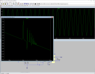
"New schematic: Reasonable voltages, but in pentode mode the biasing is too cold, 14W tube dissipation, it runs out of current very quickly, distortion is very high. I simulated it, increased B+ to 400V and reduced the cathode resistor to 220 ohms to bias the EL34 hotter, it works, distortion is a bit high though (this is, as usual, simulation. Your result may be different)
Attachments
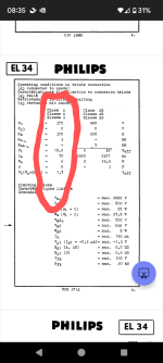
Using Philips recommendations, triode strapped, 375V B+, 370 ohms bias (24W total dissipation), 6H9C as first stage gives a decent result.
Looks like Aliexpress kits are like a box of chocolates, you never know what are you going to get 🙂
Looks like Aliexpress kits are like a box of chocolates, you never know what are you going to get 🙂
^This^Solid state rectifiers are a way better choice, and there is another way to fix the over-voltage situation: place one or more zener diodes where the 200 Ohm resistor (R1) is. You can drop about any voltage to like as long as you get the power dissipation right.
https://www.digikey.com/en/products/detail/solid-state-inc/1N3327B/11617650
Looks like Aliexpress kits are like a box of chocolates, you never know what are you going to get 🙂
It all depends on your seller.
- When in doubt, use the chat feature to ask for information before buying. If they respond quickly (adjust for your time zone) and they are friendly and can answer basic questions, that's a good sign. I bought a camping tent a few years ago not because it was cheaper but because I loved the way it was made. There wasn't anything else like it. The seller actually wouldn't sell it to me until I answered questions using chat about the weather where I intended to use it. Best tent ever and a great price! So for this kit, I chose a seller who was both responsive and helpful. We will see what is in the box.
- Research, understand, and accept culture differences. The relationship between buyer and seller is not what you may be used to.
- Don't expect perfection.
- If any parts are missing or there are major problems, AliExpress is excellent at resolving disputes. They hold your money and don't give it to the seller until you agree that everything is OK.
- I have bought three DACs and a number of op amps including a discrete op amp from seller Akliam. They are very knowledgeable and very responsive. They actually have consulted with the factory that builds them to answer some technical questions for me. I love all of the DACs.
- Douk Audio has an excellent reputation, but they charge more than any other seller, and the difference is significant.
- The Huaji Audio EL84 amp kit is good and well proven. Huaji Audio is an actual company in China. When I broke an output transformer while building (my fault) the factoy was between production runs. They told me that they had transformers on the shelf but wouldn't sell to me because they could not match up a pair. 10 days later, they did, but by then I had repaired the hair-like winding that I broke.
- The schematic in post #1 is the one that was emailed to me, with the two 150Uf caps. We will see if that's what's in the box.
- I have gotten very good at translating Chinese to English. You have to run OCR on it to extract the characters and then paste them into several online translators. I translated the 67 pages of directions for the Huaji Audio kit and posted them here as a public service. The name of this SE kit translates to "Fire of the Dragon" or a better translation is "Dragon Fire" I think. Let's hope that's not what happens when flipping the power switch! 😵
I want to thank everyone participating here. I am learning so much. This is the first time I have ever looked at a tube rectified power supply, and it's very tempting to try it just so I can say that I tried it. The 5Ц4С tube is only $5, it helps me bleed of voltage, it's indirectly heated, and it seems that SE amplifiers don't require a whole lot of "on demand" power. However, there are a lot of advantages to SS as pointed out here, and that's what I came here to ask. I think I should have titled the thread "teach me about tube rectification vs. solid state" though. I had already convinced myself to use SS before I came here, and now I am looking at both options now that I know more about both.
I'm not concerned about the audio circuit right now as I can make it whatever I want when the time comes. However, I'm very glad that I asked about the B+ voltage that we are trying to achieve as it now appears that I don't have to drop as many volts as I thought, assuming the transformer actually is 320-0-320V. I am focused on the proper voltages from the power supply first. Without a power supply that works, nothing else will work, and it's a place where you really don't want to blow up something, like a power transformer. I won't be using the included power supply caps regardless of their size because I don't trust them. The second Huaji Audio kit will be arriving about the same time, and I will take whatever parts come with it and apply them to this "Dragon Fire" SE amp as needed as they are known good quality parts. The second Huaji Audio will be getting a complete stock of top quality parts from Mouser this time, and a good volume pot. The Huaji Audio volume pot will go into the "Dragon Fire" SE amp as it isn't bad. I have a lot of EL34 tubes on the shelf. So there is a method to my madness.
Now I have to go back through these posts. So much to learn. I had no intention of learning about tube power supplies, but it's good that I am learning!
Happy Thanksgiving to those who are celebrating today.
Last edited:
Just in case I gave the wrong impression, I shop a lot on Aliexpress, and there are plenty of good suppliers. I have bought output transformers, russian tubes, smps etc.
I do work for a Chinese company, therefore google translate is something I use daily, no problems with that 🙂
Happy Thanksgiving everyone!
I do work for a Chinese company, therefore google translate is something I use daily, no problems with that 🙂
Happy Thanksgiving everyone!
I've actually worked with this rectifier tube quite a bit and it's actually quite good if you obey the first capacitor limits. Replace that first oversize 150uf with a 22uf, leave everything else just like is shown above, and it will work just fine. The reports of short life for that tube are in amps like this, with a giant first cap. These designed in China amps are famous for doing this! Note the data sheet even says 5uf is the limit. I've found you can fudge this a bit, up to 22uf, if you aren't running the tube at it's max current rating.What is the solution to this problem without adding a whole lot of complexity to the power supply?
1) I want to replace the Russian 5Ц4С with solid state rectification in this power supply, and I don't want to jack up the voltage. The voltage drop across the rectifier tube is about 45 volts, correct? How do I get rid of the excess voltage from solid state rectification without harming the power supply performance and preferably improving it? If I can use solid state and get a performance improvement at the same time, great!
2) I also need to drop a little more voltage because the transformer is rated for 110V and I have 120V from the wall. It's a single-ended, 6H8C - EL34 amplifier, and I don't know what the current draw for that might be. The choke is rated at 200mA. Specifications call for 310V and 285V out as shown. Wall voltage is 120VAC going into a transformer designed for 110VAC.
3) If I decide to use tube rectification, what is the expected lifespan in hours for a longer life replacement tube, and which tube type to use? 5Ц4С is rated only 500 hours. I really want the convenience of solid state like my other three tube amps. Only 500 hours is a real pain, and the cost adds up as I put a lot of hours on my system.
I can make simple changes, as the amplifier hasn't been built yet, but I do not want to add a whole lot of complexity to this schematic. There has to be some reasonable solution.
Let's not discuss the merits of or problems with the audio circuit here please. Let's save that for later if I build this kit. Let's focus on the power supply as that is all that matters right now. Power supply design is a subject of its own and a critical skill, so that's why I started this thread.
View attachment 1236896
View attachment 1236899
If you then find that rectifier tube has a short life after doing this change and you actually like the way these cheap amp sounds (I doubt it's gonna sound world class, likely has super cheap output transformers) then look at a more robust solution. Again, I've worked on a bunch of amps using this tube and that "service life of at least 500 hours" doesn't reflect how long these last if used correctly. It will likely outlast the output tubes wired as I suggest.
Going directly to SS takes a couple of things off the table. The tube rectifier isn't going to introduce switching noise that SS diodes can introduce and also provides a slow ramp up of the B+ high voltage. Plus to implement what I am suggesting will cost you one 22uf cap...
I haven't found a data sheet with much detail like that. Would you post the one you have or provide a link?Note the data sheet even says 5uf is the limit.
Thanks Stephe. I have found some of your comments about the rectifier tube in my online searches. Good information as usual. If it's reasonably reliable I might try it for no real reason other than to say that I once tried a tube rectifier.
I don't want to get into the audio circuit yet, but as long as we are here @stephe what would be your preference for B+? I need to target the "best" value for the output of the power supply.
Your YouTube channel is great. I learn a lot there, and I especially love it when you dig into a Chinese amp and fix it.
Yes, post #1. I translated it from Russian by running OCR on it and then using online translators.
I don't want to get into the audio circuit yet, but as long as we are here @stephe what would be your preference for B+? I need to target the "best" value for the output of the power supply.
Your YouTube channel is great. I learn a lot there, and I especially love it when you dig into a Chinese amp and fix it.
posted datasheet "Filter capacity 5uf"
Yes, post #1. I translated it from Russian by running OCR on it and then using online translators.
Last edited:
340-350V B+ should work OK, you might try lowering the cathode resistor to 250ohms later? Build it and measure the cathode voltage you see on the actual amp, I've learned what is expected based of data sheets doesn't always = reality on the actual amp. For an SE amp, I like seeing 85-90% of the tubes dissipation limits. And we don't know what the primary impedance of your OT is do we? That would tell us more about where the voltage across the tube should be.
Attached is where I ended up with the little Reisong A12 to get it sounding good and making decent power. It used UL transformers and you are running this as a pentode with GNFB so might have to adjust for that. And God forbid, I used plate to plate Schade feedback in my mod. I'm sure I will get burned at the stake for doing that!

Attached is where I ended up with the little Reisong A12 to get it sounding good and making decent power. It used UL transformers and you are running this as a pentode with GNFB so might have to adjust for that. And God forbid, I used plate to plate Schade feedback in my mod. I'm sure I will get burned at the stake for doing that!
And we don't know what the primary impedance of your OT is do we?
It is supposed to be 3.5k, but 1) They are not here yet so I can't yet see if they are marked, and 2) I have no way to measure it to be sure.
you are running this as a pentode with GNFB so might have to adjust for that.
Yes. I'm not focusing on the audio circuit for now, but yes that is the goal, pentode with GNFB. So B+ for that configuration.
The above post should all work fine. Later after you get it all working, one mod to investigate might be a regulated screen supply.
- Home
- Amplifiers
- Tubes / Valves
- 5Ц4С replacement with solid state?