
If that is the case, there is your answer.The Uframe has twice the delta path and so starts rolling off at 6 db per octave an octave later.
But that is a bit of a skewed comparison to use as a general statement.
For a dipole, the only variable IS that delta path.
But yeah practically that can give certain design choices. 🙂
Regarding this:
The pathlength distance between front and rear output and the observation position is what determines the PHASE difference between the two sources at that point in space, and that is what is determining the amount of cancellation at the listening location (or anywhere in the far field).
Increasing the front-rear pathlength difference does not make is "less of a dipole", it just moves the location of the dipole peak lower in frequency. For illustration purposes, assume that the driver passband extends all the way down to DC. If we take this driver and compare two dipoles, dipole-A with a pathlength Da and dipole-B with pathlength Db, where Db > Da. The SHAPE of the frequency response for each dipole system will be exactly the same in the far field. The response for dipole-B with the longer pathlength Db will be shifted to a lower frequency, e.g. the dipole peak occurs at a lower frequency. For any given frequency below the dipole peak its SPL level will be higher than for Dipole-A. Both are still 100% dipoles.
For a real world system, there is also the driver's own response around and below Fs that also influences the low frequency rolloff.
So the only way to get more output, is to make the source work harder, or make the path length between front and back bigger, so the cancellation isn't as strong. (aka, making it less of a dipole)
The pathlength distance between front and rear output and the observation position is what determines the PHASE difference between the two sources at that point in space, and that is what is determining the amount of cancellation at the listening location (or anywhere in the far field).
Increasing the front-rear pathlength difference does not make is "less of a dipole", it just moves the location of the dipole peak lower in frequency. For illustration purposes, assume that the driver passband extends all the way down to DC. If we take this driver and compare two dipoles, dipole-A with a pathlength Da and dipole-B with pathlength Db, where Db > Da. The SHAPE of the frequency response for each dipole system will be exactly the same in the far field. The response for dipole-B with the longer pathlength Db will be shifted to a lower frequency, e.g. the dipole peak occurs at a lower frequency. For any given frequency below the dipole peak its SPL level will be higher than for Dipole-A. Both are still 100% dipoles.
For a real world system, there is also the driver's own response around and below Fs that also influences the low frequency rolloff.
We are now starting to repeat the same thing. 🙂
Get the highest xmax and Sd you can get, ideally with a very high BL (low Qt) and just EQ it.
At those lower frequency it's basically only xmax*Sd that counts (plus a tiny bit of sensitivity).
In a day and age where amplification and EQ is easy and cheap, I personally don't see that a problem anymore.For a real world system, there is also the driver's own response around and below Fs that also influences the low frequency rolloff.
Get the highest xmax and Sd you can get, ideally with a very high BL (low Qt) and just EQ it.
At those lower frequency it's basically only xmax*Sd that counts (plus a tiny bit of sensitivity).
by contrast, the undamped Uframe
Attachments
The pathlength distance between front and rear output and the observation position is what determines the PHASE difference between the two sources at that point in space, and that is what is determining the amount of cancellation at the listening location (or anywhere in the far field).
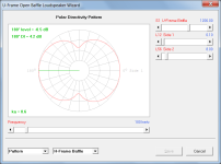
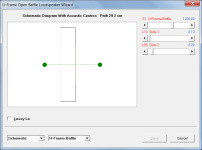
Just to clarify, in the case of the power response the path length is the distance between the two acoustic centres, as shown by the dotted green line in the attachment.
Attachments
^ go to A3 https://www.linkwitzlab.com/models.htm
Baffle width determines the dipole range, best seen with dipole null (above which dipole radiation disappears). Driver diameter has minimal effect with exeption of nude driver.


Baffle width determines the dipole range, best seen with dipole null (above which dipole radiation disappears). Driver diameter has minimal effect with exeption of nude driver.
Last edited:
Correct. Cardioid looks good on paper. But speaking about lowest frequencies.Directivity Index as dipole but has little output to front wall. Which is dipoles bigest problem at low end as ussualy people want to push closer to the wall. At a very low end seems cardioid is the way to go. But this works while cardioid is not very close to front wall. Otherwise it becomes more or less the same as monopole pushed against the wall just with lower output.imagine the speaker emmiting to front hemisphere only. So pushing back to the wall this and monopole will become the same just monopole about 6db more output.Cardioid avoids front wall reflection in only one of six dimensions... but a dipole helps with sidewalls and to some extent floor and ceiling reflections too. I haven't heard cardioid bass but in midrange it is not much different from typical large monopole. Dipole wide range excites reflections in totally different manner and is more sensitive to placement than others - and sounds different too!
It seems though that with a nearby sub or a Uframe of any depth, you can't avoid cardioid-like response in the low end.
That isn't necessarily a bad thing. I was able to find a "nice" overall response using the Uframe only to 270 Hz so I extended its depth from 8cm to 18 cm, which made it even more cardioid-like but recovered some of the maxSPL I gave up when I was using the Uframe up to 300 or 400 Hz. It reverts back to dipole response above 100 Hz. I have less concern about audible cone resonances if the 15OB350 is used only up to 270 Hz

The overlays in the Power & DI graph are the in-room responses for angles +/-10 and 0 degrees
The middle driver spans 100 Hz to 400 Hz. The baffle is 314mm wide at its height.
The Uframe is low passed at 270 Hz.
That isn't necessarily a bad thing. I was able to find a "nice" overall response using the Uframe only to 270 Hz so I extended its depth from 8cm to 18 cm, which made it even more cardioid-like but recovered some of the maxSPL I gave up when I was using the Uframe up to 300 or 400 Hz. It reverts back to dipole response above 100 Hz. I have less concern about audible cone resonances if the 15OB350 is used only up to 270 Hz
The overlays in the Power & DI graph are the in-room responses for angles +/-10 and 0 degrees
The middle driver spans 100 Hz to 400 Hz. The baffle is 314mm wide at its height.
The Uframe is low passed at 270 Hz.
I've spent most of the time since my last post learning ABEC and then using it to model dipoles and U-frames.
ABEC has led me on a merry chase, first with me learning its syntax, then learning to do parametric models with lists of nodes rather than CAD drawings, and learning the necessity of getting "normals" to point in the right direction and learning the necessity of using enough EdgeLength resolution to avoid gaps in the mesh especially at the junction of driver diaphragm with baffle; all this learning being done the hard way🙂
Only then could I study the problem I was trying to solve: a full range open baffle that works in my space with minimal boundary interference in a small footprint. What I thought would work at the start is very different than what ABEC and Vituix now predict will work.
Thanks to @ctrl from ASR for giving me a leg up with a template and helping me a couple of times when I was stuck. It was his simulations on ASR that were linked earlier in this thread.
At the start of the ABEC project, my concept was a tall baffle wide enough at the bottom for a 15" woofer, tapering to just fit an 8" coax driver at the top. I intended to leave the top half of the coax driver unbaffled in an effort to extend dipole response up to the crossover to the CD/tweeter. I found I couldn't model this half un-baffled driver in ABEC, at least not easily, so I settled for minimal baffling around it.

Running the sim, I saw a serious defect in this response - n
 No baffle above combined with big baffle below distorts the vertical response of the driver. One might argue that throwing a null at the floor in front of the speaker is a good thing but looking at the horizontal response fields shows a much more serious defect - no nulls out to the sides even well below XO.

Thus, the first major concept revision.
Running the sim, I saw a serious defect in this response - n
Thus, the first major concept revision.
I then followed a trail of simulations of minimal baffles. the best looking one to my eyes is the 2nd one from the bottom derived by truncating the tips of my rotated square baffle. I don't understand why this one is so much better than the others and that makes me uncomfortable but all of these shapes are little more than pasties on a naked driver and thus easy to change/modify.

Next up is the woofer. The original concept was a single 15 aided by separate subs. A midwoofer joined the party at one point to improve the verticals around XO between woofer and coax. When I compared ABEC sims to Vituix dipole approximations, I found Vituix was hugely optimistic. At the same time, I got the idea of using a sealed shallow mount 12" sub at the bottom of the array, in back , with the dipole(s) simply playing over top of it. The woofer of choice changed from 15OB350 to double 12OB150 to double Purifi PTT10 in the interests of narrowing the baffle, finally to a single PTT10 when I realized how much they cost. In my Vituix system simulation, I saw that a single woofer placed at the midpoint between the two prior woofers it replaced worked just as well, directivity wise. Using a sub at bottom meant that a single PTT10 was sufficient.

All of these simulations are certainly interesting, and food for thought, but I think they are missing one important item: the influence of the floor boundary. The floor will act like any other boundary (e.g. walls) and as you probably know the general rule for dipole systems is to keep boundaries at least 1m away. But that is based primarily on the front wall, where the pathlength difference between the sound reflected off of that boundary and the listener is twice the distance to the boundary because the sound travels first backwards and then forwards again. For the floor this is not the case and this means that the floor reflection will be "too close". I have rationalized that there are different behaviors that depend on the frequencies involved. IMO the most problematic frequency range is around 200-300Hz and this is exactly where the "floor bounce" dip will occur when the driver reproducing those frequencies is elevated above the floor when midway up the baffle like in some of your models. Since there is not feature for this, I assume your model is leaving out that important part of the acoustic response from the speaker in a real world room. So why do you hear it? The pathlength difference is below the limit of 4msec and so is part of the "direct sound" in your mind even though it is a reflection. My way of mitigating this issue is to locate the driver for the band that will reproduce up to about 300Hz at the floor. This makes the reflection and direct sound very close in time, and the dip is also pushed higher in frequency to just above the 300 Hz passband edge. Then there is the next band higher in frequency to think about. The driver (let's call it the midrange) will be higher above the floor near ear level. This makes the lowest dip from the floor reflection occur below 300Hz, which is below its passband. Above that there are shallower dips and peaks from interference of the floor reflection, however, IMO the brain easily gets "used to" such a pattern and can ignore it. This is because the hearing apparatus has evolved to make sense of sounds in reflective indoor spaces and it has a way of interpreting the interference pattern as source elevation and not as an actual timbre change to the source. This outlook on how we hear loudspeakers in room is what currently guides how I choose to place drivers in my speaker designs, and I put the woofers on/at the floor level, the midrange is as high above the floor as is practical, and then the tweeter goes somewhere around ear level above or below the midrange.
The other arrangement that might work but that I have not attempted is a multi-driver vertical array for the band covering up to 300Hz or so, e.g. four or more 6" to 8" class drivers stacked vertically in a baffle, since this would help to smear out the floor bounce. These could be put in a relatively narrow or tapering baffle with the midrange on top like a WWWWTM or WWWWWTM, etc. but the speaker would probably still need a subwoofer below 50-60 Hz for any real bass authority. With a crossover point that low, the sub can be placed anywhere in the room and does not need to be part of the main speaker(s). OTOH, at some point the midrange design height will movw past (above) the midway point between the floor and ceiling and then the problem gets worse again because of the ceiling reflection!
If you are concerned about the problems with the radiation pattern from a tall narrow baffle that you mentioned in post #17 you might model that again but with an open "hole" in the baffle just below the midrange. I bet that would help the pattern shape a lot. The less baffle there is, the better the pattern! This is why I eventually threw out the baffle and went nude for the midrange and tweeter...
FYI I did some measurement back in 2012 or so where I mounted a driver at the top edge of the baffle (half in half out IIRC) and then about 2" at a time moved it up above the baffle edge. When there was about a 4" gap between the edge of the driver frame and the baffle edge it was as if the driver was "nude". Then you can use as massive a main baffle as you like mount the midrange above it (somehow) and then place the tweeter at the baffle top just below the mid.
Last edited:
Yes, the floor is indeed important and I take it into account in my Vituix system simulations which I have yet to show. I use ABEC to generate Vituix polars for each driver, then sum drivers together in Vituix. All my ABEC models are parameterized so I can easily tweak things, provided I'm willing to wait from several minutes to half an hour for results.
I created Vituix polars for every one of those baffles I showed and a few that I didn't and looked at the boundary interference/support and constancy of the directivity. Here is the power-DI-inroom response for my current concept. The dashed overlay is the in-room response with floor, ceiling, and wall reflections enabled. The speaker is 1m from front and side walls and toed in 40 degrees. You can see the floor bounce dips are right where you expected them but not very deep. The driver for 100-400 Hz is 425mm above the floor. The coax is at 900 mm. If I move the woofer lower, then CTC at XO to the coax gives me more sitting vs standing variation around that XO than I would like.

I tried simulating the floor in ABEC but it gave me difficulties that I chose to sidestep rather than beat my head against. I have Vituix sims that include floor and wall image drivers for the woofer, which give more info than simply looking at in-room with reflections enabled.
I created Vituix polars for every one of those baffles I showed and a few that I didn't and looked at the boundary interference/support and constancy of the directivity. Here is the power-DI-inroom response for my current concept. The dashed overlay is the in-room response with floor, ceiling, and wall reflections enabled. The speaker is 1m from front and side walls and toed in 40 degrees. You can see the floor bounce dips are right where you expected them but not very deep. The driver for 100-400 Hz is 425mm above the floor. The coax is at 900 mm. If I move the woofer lower, then CTC at XO to the coax gives me more sitting vs standing variation around that XO than I would like.
I tried simulating the floor in ABEC but it gave me difficulties that I chose to sidestep rather than beat my head against. I have Vituix sims that include floor and wall image drivers for the woofer, which give more info than simply looking at in-room with reflections enabled.
To go back for a minute - the first set of simulations was to find a baffle shape for which the dipole response (nulls to the sides) extended all the way to the crossover to the CD.
The purpose of the second set of sims was to choose between dipole and U-frame for the woofer. I showed the progression that led me to a U-frame 118 cm deep that retains the desired directivity past 400 Hz, its nominal low pass. I will show the polar maps later. I realize now I skipped over the 15OB350 and 12OB150 modelling I did. I switched from 15OB350 to 12OB150 to get a narrower baffle when I realized that with a sub, I didn't need all the volume displacement of the 15" driver. I went down further to the PTT10 because I thought the 12" crowded the baffle edges too much. Initially, I had two PTT10s but dropped one when I considered the cost.
These PTT10 simulations deserve a closer look. The top 2 dipoles deliver only 48 db at 100 Hz. The 3rd delivers about 4 db more, apparently from the support of the subwoofer cabinet behind it. The two U-frames deliver progressively more SPL.
The bottom simulation has 100 mm deep sides and top around the woofer plus the 18 mm baffle. This is as deep a U-frame I could do and still have a response with the desired directivity past 400 Hz. It shows significant peaking due to pipe resonance which you can see is very equalisable. Because of the peaking, the roll-off below peak is more than 6 db per octave but the net at 100 Hz is almost 10 db better than the dipoles. HornResp models confirm these results. Its not exactly apples to apples but the results are very similar. OTOH, the Vituix models I had been using are wildly optimistic in terms of the SPL delivered at the low end. They predict a rolloff starting around 200 Hz rather than 400 Hz and ignore the pipe resonances.
In the system, I will let the PTT10 play as low as it can cleanly. That will be somewhere between 60 and 80 Hz. When you consider that it takes 8x the displacement to go an octave lower, it doesn't take much raising of the high pass frequency to remain within the linear range of the driver.
The interaction between the subwoofer and the U-frame is another very interesting story. One can simply crossover between them or overlap the subwoofer with the U-frame up to perhaps 120 Hz. With a crossover, you get dipole response down to the XO frequency. With overlap, you can tune delay and phasing to get cardioid-like response in the overlap region. In my room sims, I see a boundary null near 100 Hz, which can be minimized this way..
I don't really have a lot of interest in audio anymore but a couple of things regarding low frequency and rooms. First, most of what you read about dipoles and cardioids is based on the assumption that the listening distance is at infinity and in free space. But what happens when you aren't far from a dipole or cardioid source. I looked at this some time ago here: http://musicanddesign.speakerdesign.net/Dipole-axis.html Of interest is that as the listening distance becomes less, the 6dB roll off stops at higher and higher frequency. This is because as you get closer the difference is SPL level from the front and rear sources differs and the front source becomes dominant. The closer you get, the higher the frequency where this happens. But again, this is a free space consideration.
In a room it makes much more sense to look at the modal response where each driver (or source) is consider separately with different position and phase. Again, I looked at this approach in the past here: http://musicanddesign.speakerdesign.net/Dipole_modesA.html
Lastly is the issue of crossing over between sources with different radiation patterns. The transition depends on the order and type of crossover. That can be explained here: http://musicanddesign.speakerdesign.net/craw_cross.html But again this is basically a free space consideration for low frequency crossovers (woofer to subwoofer).
Just though these references might be helpful. Ignore the math. Look at the figures and associated text.
One question- with u -frames the quarter freq is noted as a concern due to resonances. Doesn't this issue become less of a concern if the walls of the u-frame are not parallel? That is, if the u-frame flares towards the rear with non-parallel sides, resonances do not form at the usual 1/4 wavelength?
+1 on this. I have also created some two-monopole models of dipole sources that take into account the difference distances to front and rear sources and found the same thing. For a fixed listening distance this effect is more pronounced as the baffle becomes larger. But this also causes a problem in that the bass response is somewhat position dependent, assuming in the listening space you can move between "near" and "far". For example my home is open plan, and there is a notable difference in the relative bass level between the listening position and when I am 40 feet away. To mitigate this I reduce the size of the front-to-back pathlength (make the baffle smaller) but that also reduces the low bass capability. Combined with the 8x per octave displacement rule, this suggests that a monopole type subwoofer crossed over at 60Hz (or as low as possible) to a modestly sized dipole panel will work well, and I have found this to be the case.I don't really have a lot of interest in audio anymore but a couple of things regarding low frequency and rooms. First, most of what you read about dipoles and cardioids is based on the assumption that the listening distance is at infinity and in free space. But what happens when you aren't far from a dipole or cardioid source. I looked at this some time ago here: http://musicanddesign.speakerdesign.net/Dipole-axis.html Of interest is that as the listening distance becomes less, the 6dB roll off stops at higher and higher frequency. This is because as you get closer the difference is SPL level from the front and rear sources differs and the front source becomes dominant. The closer you get, the higher the frequency where this happens. But again, this is a free space consideration.
In a room it makes much more sense to look at the modal response where each driver (or source) is consider separately with different position and phase. Again, I looked at this approach in the past here: http://musicanddesign.speakerdesign.net/Dipole_modesA.html
Lastly is the issue of crossing over between sources with different radiation patterns. The transition depends on the order and type of crossover. That can be explained here: http://musicanddesign.speakerdesign.net/craw_cross.html But again this is basically a free space consideration for low frequency crossovers (woofer to subwoofer).
Just though these references might be helpful. Ignore the math. Look at the figures and associated text.
- Home
- Loudspeakers
- Multi-Way
- Dipole and Uframe models and discussion re' Live Edge Dipoles