The THS6012 is very similar to TPA6120.
You can rest assured its the same die inside, just tested differently - https://www.diyaudio.com/community/threads/what-is-wrong-with-op-amps.169484/post-4887791. Note that @johnc124 works for TI in Tuscon so I reckon he qualifies for 'the horse's mouth' 😊
Spice model for THS6012 here : https://www.ti.com/product/THS6012#design-development

H
HAYK
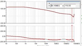
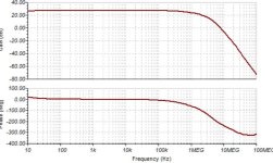
It was a child game to stabilize this amp. Unlike the precedent, this amp has two pole very high frequencies in UHF band. The loop gain is monstrous 120db, maybe usual for Minek, for me, it is the first time I am dealing with 60Mhz 0db with 100db NFB @20khz.
I offered 70° PM.
I added diodes to limit the output current, here it is 6A with 3 diodes it limits 8A. I must add diodes on the output.

I offered 70° PM.
I added diodes to limit the output current, here it is 6A with 3 diodes it limits 8A. I must add diodes on the output.
Attachments
H
HAYK
Alexander's amplifier in post 17. May be with AD826. The distortion on the supplies is much higher than the output, not the case with CFA amp.Nah ! Magic smoke. Built this ... (below) , you can play with just about any op-amp.
OPAxxx gave the very fast slew (it is a CFA circuit). Chip slew is the limiting factor...
OS
H
HAYK
The TPA6120 needed 2.2nF for stability, it destroyed the slew rate to 2v/us.
I replaced back the AD8007 for the IPS, it has about 104db instead of 120db but no any compensation with BD139,140.
I don't think the size of the PCB will more than 70x30 mm.
I replaced back the AD8007 for the IPS, it has about 104db instead of 120db but no any compensation with BD139,140.
I don't think the size of the PCB will more than 70x30 mm.
Attachments
The problem with building it will be these extra power supplies referencing the output....
Extra cost, and you will need 2 of them, for 2 channels...
Extra cost, and you will need 2 of them, for 2 channels...
H
HAYK
They are bootstraped supplies it needs each 2 resistors 2 capacitors and a zener.
Optional is to use 4 x5v tiny chargers.

Optional is to use 4 x5v tiny chargers.
Last edited by a moderator:
H
HAYK
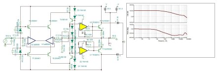
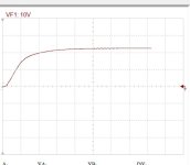
This Amp has two stability problems to solve. The overall feedback and each output feedback. The overall is excellent but not the outputs. I decreased the gain by 3 fold, added base stopper 5 ohms still I get very slight oscilation as can see bellow, the curve is not clean. The slew rate limits about 80v/us, honorable.
No doubt I will big trouble with the PCB.
No doubt I will big trouble with the PCB.
Attachments
Hmmm...added base stopper 5 ohms still I get very slight oscilation
Can you try very slow output devices like bd911/bd912?
H
HAYK
I tried with mjl21193, 94, it is worse.
The tpa6120 with very high transresistance is too wild to tame. I need to learn how to compensate a CFA circuit.
The tpa6120 with very high transresistance is too wild to tame. I need to learn how to compensate a CFA circuit.
H
HAYK

It’s not a bit surprising there are more stability problems with that output stage compared to a normal emitter follower. With the emitter grounded IT becomes the common terminal and the output stage runs open loop (loses its 100% local feedback). You now have more poles to deal with. More open loop gain, so even more distortion correction is possible. IF stability can be maintained.
H
HAYK
H
HAYK
Two loops, overall loop to control the output voltage and the local loop to control output current. If unloaded, only the voltage feedback is active.It’s not a bit surprising there are more stability problems with that output stage compared to a normal emitter follower. With the emitter grounded IT becomes the common terminal and the output stage runs open loop (loses its 100% local feedback). You now have more poles to deal with. More open loop gain, so even more distortion correction is possible. IF stability can be maintained.
H
HAYK
H
HAYK
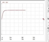
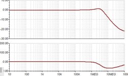
I modified the circuit to 2 pole compensation and got stable without the lead capacitors on the outputs..
The step responses with and without input filter are shown ,200ns/div, as well as closed loop frequency response.
I will switch to LT for more detailed analysis.

The step responses with and without input filter are shown ,200ns/div, as well as closed loop frequency response.
I will switch to LT for more detailed analysis.
Attachments


H
HAYK
H
HAYK
A better choice than TPA6120 is OPA2670. It is 5000v/us, 420Mhz. No info about distortion but the price for 1k is $1.4 from TI. Mouser asking $4, Ali sels 5 for $20.
Unfortunately I couldn't find spice model.
Another option is THS6002. It has 2 drivers, 2 receivers , each with its own supply. Ti is asking $9 1k, mouser wants over $16.
Unfortunately I couldn't find spice model.
Another option is THS6002. It has 2 drivers, 2 receivers , each with its own supply. Ti is asking $9 1k, mouser wants over $16.
H
HAYK
The high current, high speed line driver, opa2673 seams the be the most popular. SR 3000V/us 600Mhz BW and costs $0.95 from TI, the double from mouser. I have the spice model in Tina. It is 4x4 mm dust cooled by PCB, I wonder if a DIY can solder it with ordinary soldering iron.
H
HAYK
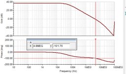
I tested the opa2673. Unlike the predecessor, it is stable with maximum gain R2=10ohm.
The distortion is 0.002%@20khz 2A, with 510ohms it is 0.02%, biased 3A. This value is going to be added to the open loop distortion of the IPS/VAS to be corrected by 100db.

The distortion is 0.002%@20khz 2A, with 510ohms it is 0.02%, biased 3A. This value is going to be added to the open loop distortion of the IPS/VAS to be corrected by 100db.
Attachments

Last edited by a moderator:
- Home
- Amplifiers
- Solid State
- 1 EF AMP