Yes, sorry -- that was confusing! I realized I hadn't tested the transformer in the center tap configuration, so thanks for verifying the similar measurement. I have the 2021 version SE board -- which uses R*, C*, and C** as the snubber parts.
I'm using a 20.5R resistor at R*, .15uF at C* and .01uF at C** with the AN-0218
Caps are the EPCOS B32529 series as recommended by Mark in his Quasimodo article.
I'm using a 20.5R resistor at R*, .15uF at C* and .01uF at C** with the AN-0218
Caps are the EPCOS B32529 series as recommended by Mark in his Quasimodo article.

it's written several times that you need to ignore snubber option in first batch of pcbs - my error, didn't check the fact that each half of secondary is needing own snubber cell
error rectified in second batch
error rectified in second batch
Received my IP balanced kit from the DIYA store today. Thanks to ZM and the store guys.
Well, and I'm a dodo. Mine's the AS-0518 .... oops.Yes, sorry -- that was confusing! I realized I hadn't tested the transformer in the center tap configuration, so thanks for verifying the similar measurement. I have the 2021 version SE board -- which uses R*, C*, and C** as the snubber parts.
I'm using a 20.5R resistor at R*, .15uF at C* and .01uF at C** with the AN-0218
Caps are the EPCOS B32529 series as recommended by Mark in his Quasimodo article.
I think that's awesome! I absolutely adore this pre-amp and its balanced "big brother". One of the reasons I asked, is while our impression of the sonics mimic each others', my memory of the distortion differed from yours.It may not have shifted / changed it is pure imagination.
The subjective listening test without any technical evidence was that sound was slightly "warmer" and more dynamic and also a more "vibrant" bas response.
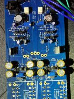
So... I fiddled around a bit and reran some stuff. Also... this is NOT to show differently, but it's just an example of one and one only Iron Pre that I happened to be fiddling with today. This one could be a unicorn. I attached a few I/O's and a donut ... and let 'er rip.
-------------------------------------------------------
For everyone to get a giggle...
This should be a demonstration of the worst performance one could reasonably expect out of an Iron Pre that was built 'to spec'. This was literally tossed together in <30 minutes. Edited to add... just the test set-up, pot, I/O, and PSU. The board was built years ago. I/O is literally over a foot long. Pot was wired and set to max. Pic is not for laughter, but to demonstrate that anyone that actually takes some care with their build... WILL likely get better objective performance.
Why do I say that?... b/c even "as bad as it can probably be", it's pretty darn amazing. I haven't looked at ZM's measurements in years... but here's a set of quickies.
For my fellow 🤓 s out there.
I left a bunch of the display references on... I had been fooling with another FE, so the PWR would be if this pre was going straight into a follower (like the F4)... which by the way works absolutely brilliantly, IMO.
Here's a few FFT's at 6dB gain at various inputs/outputs. Input was 0v5rms, 1Vrms, and 2Vrms. Note, I had to bring the noise floor up a bit for the last measurement due to the higher output level of the last measurement. I also forgot to turn on the "pointers", but you get the idea. Very low (relatively speaking) distortion. If one could call one of the phases dominant, it would be 3rd.


Here's a few at 12dB. I ran a few examples if someone had a "really hot" source. 0V5, 1V0, 2V0, and 2V5. I'd say roughly the same ratio of 2nd to 3rd, but maybe yes a bit higher 2nd in relation. Forgot to turn on the "pointers" again for the last one.


Then... if someone had a really, really hot source and wanted to drive an F4 to voltage clipping... here ya go...


Such an awesome pre-amp. I promised to show the non-glamour shot... here ya go. This is exactly the state it was in during measurement. Everyone should do better than me... 🙂 🙂
 Sounds absolutely fabuous.
Now... I am curious about fiddling with some voltages... @nashbap inspired me...
All measurements above were with V+ and V- at 15V0
ZM - this is the new Fugly.

Last edited:
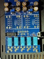
Powered up my board for the first time. Everything biased correctly (+/- 15V rails, DC Offset = 0).
I'm getting weird behavior from the input selector. The RLY+ / RLY- reading is 13.5V (using 12V relays), and I have continuity from the Twister to the main board. The LEDs are installed. When I rotate the switch -- starting fully counterclockwise, I get no response until I hit the 5th contact on the switch -- at which point all 5 LEDs light up. No clicking on the relays except at power up and power down. Everything appears to be installed correctly, ZD1 and ZD2 are the correct values (I removed ZD2 and measured it to make sure I didn't mix them up).
No iron installed on the board, and all the inputs and outputs are disconnected.
@ItsAllInMyHead ,
Is that a single ended iron pre you are showing measurements of? That is what would expect to see on a balanced build (dominant 3rd harmonics), but my balanced build, while measuring extremely well, shows dominant 2nd harmonics. It makes me wonder if I've hooked up the attenuators improperly. I have each board going to a separate stereo pot, and each channel on the board going to a separate channel on the pot.
Is that a single ended iron pre you are showing measurements of? That is what would expect to see on a balanced build (dominant 3rd harmonics), but my balanced build, while measuring extremely well, shows dominant 2nd harmonics. It makes me wonder if I've hooked up the attenuators improperly. I have each board going to a separate stereo pot, and each channel on the board going to a separate channel on the pot.
Here are some plots taken with my Focusrite Gen3 1khz sine 1.0v

 input.
Numerical differences are small but certainly audible.
nash

Numerical differences are small but certainly audible.
nash
@ItsAllInMyHead:
With 12 dB setting the signal from my DAC is probably in 0.5 - 1.0V range.
If this is the case.....it could be true that there is slightly more H2......but difficult to say.....many variables......
Most important is that there is only H2 / H3.....and nothing else to "speak about".
With 12 dB setting the signal from my DAC is probably in 0.5 - 1.0V range.
If this is the case.....it could be true that there is slightly more H2......but difficult to say.....many variables......
Most important is that there is only H2 / H3.....and nothing else to "speak about".
Powered up my board for the first time. Everything biased correctly (+/- 15V rails, DC Offset = 0).
I'm getting weird behavior from the input selector. The RLY+ / RLY- reading is 13.5V (using 12V relays), and I have continuity from the Twister to the main board. The LEDs are installed. When I rotate the switch -- starting fully counterclockwise, I get no response until I hit the 5th contact on the switch -- at which point all 5 LEDs light up. No clicking on the relays except at power up and power down. Everything appears to be installed correctly, ZD1 and ZD2 are the correct values (I removed ZD2 and measured it to make sure I didn't mix them up).
No iron installed on the board, and all the inputs and outputs are disconnected.
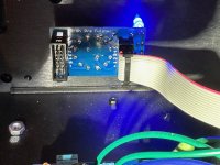
The 'twister board' is one of the things that worry me in kits like this. Is it possible that board/selector switch is backwards, i.e. on the wrong side?
Yes, SE. Pic above.@ItsAllInMyHead ,
Is that a single ended iron pre you are showing measurements of? That is what would expect to see on a balanced build (dominant 3rd harmonics), but my balanced build, while measuring extremely well, shows dominant 2nd harmonics. It makes me wonder if I've hooked up the attenuators improperly. I have each board going to a separate stereo pot, and each channel on the board going to a separate channel on the pot.
In fairness, all measurements I took a few years ago can't be trusted, so I can't tell you (yet) how any of my balanced builds measure. I also don't know what all affects the "blend" / ratio of the harmonics. Output level seems to have a slight effect. Gain seems to have a slight effect. nashbap has shown that the rail voltage has an effect. I'm not sure if the type of transformer has an effect ... etc. With the harmonics (at reasonable output levels) 80+dB below the fundamental... I'm not too sure how much it all really matters. Also, one of the reasons I've been messing with this type of thing is to see how pre-amps / FEs with various harmonic structure interact with various amplifiers / Output stages. I still like the advice Papa gave me years ago when I asked. It was something like... if you're going to add some "fun", do it in the amp vs. the pre-amp. That's one of the many reasons I like the Iron Pre so very, very much. IMO, it adds nothing. It just gets out of the way, particularly the balanced. All of that is just my opinion.
Either way, it sure is fun.
@ItsAllInMyHead:
With 12 dB setting the signal from my DAC is probably in 0.5 - 1.0V range.
If this is the case.....it could be true that there is slightly more H2......but difficult to say.....many variables......
Most important is that there is only H2 / H3.....and nothing else to "speak about".
 🙂
🙂Powered up my board for the first time
pics
that worry me in kits like this.
if you can't find enough info from schmtcs and pics, all you need is - to ask specific question
"you" = anyone
It's funny how I will go ahead assuming that I got it right and not knowing to ask the specific question. It can look right to me on an organic level, but when all connected that is when I get confused as to what happened. I will be glad for a manual for people like me. FWIW, I have my board completely done, but will not about hooking up and testing just yet.
I do appreciate the help when I finally realize that I need it though.
I do appreciate the help when I finally realize that I need it though.


Appreciate the help!
test:
remove flat cable from main pcb
short Rly+ pin on IDC header to pin "1" - that need to energize relay for Input 1
short Rly+ pin on IDC header to pin "2" - that need to energize relay for Input 2
etc
if that works, plug cable in main pcb IDC header, try repeating test but now shorting appropriate holes on other end of cable
in any case - same name pins on main pcb header and twister header must be connected with cable; easiest to trace red edge from one pcb to other
now, as I can see from pics - cable is properly oriented
which switch type you're using, and is it properly set (there is a washer having a tooth/prong to set number of positions)?
THANK YOU! This allowed me to verify that everything was installed and wired correctly EXCEPT the LEDs on the Twister board. The non-LED switch side was working correctly (I just hadn't noticed earlier -- but did once I started shorting the leads). Thanks for the great troubleshooting tips.
I apparently installed all the LEDs backwards -- reversing the LED appears to have it working correctly (at least on one -- I'll replace the rest tomorrow). Onward!
I apparently installed all the LEDs backwards -- reversing the LED appears to have it working correctly (at least on one -- I'll replace the rest tomorrow). Onward!
- Home
- Amplifiers
- Pass Labs
- Iron Pre Essentials Kits For The DIYA Store - Register Your Interest