Has anyone developed a waveguide for the SB Audience 65CDN-T yet? Or the Textreme FaitalPro 1460?
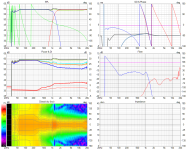
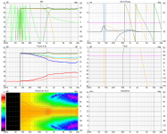
VituixCAD Simulation vs REW measurements. You can see how measuring from the front of the waveguide widened the directivity index apprx 1 dB compared to the simulation.
My statement was wrong. Original simulations were at 2 meters but my measurements were at 1 meter so I went back and recreated the simulations at 1 meter with the axis at the front of the waveguide. I thought that would make the simulation match the real world measurements but it didn't. I don't know why my waveguide measurement is 1 dB lower on the Directivity Index than the simulation. TBD
REW measurements vs new simulation (1 meter, axis at front of waveguide)
New Crossover Frequency & Center-to-Center Multiplier
Decided I preferred a 1,200 Hz crossover over a 1,000 Hz crossover. Compared each using a 444 mm/17.48 center-to-center distance between waveguide and woofer. I now prefer the sound of 1.55 wavelength c-t-c multiplier (286 mm 1.2kHz) over the 1.29 c-t-c spacing (344 mm 1kHz). In the original post (#13,919) I preferred a 1kHz crossover with a 1.29 c-t-c spacing multiplier over the 1.2 c-t-c spacing.
I compared the two crossovers using streaming TV dialogue. 1.2kHz has too much S consonant coloration and 1kHz has too much boom coloration. I chose 1.2kHz because it seems to have less coloration overall. Excess S consonant coloration also makes the TV dialogue easier to understand versus excess boom. I also preferred it with female music vocals. Still not sure I prefer it with deep male vocals or not but home theater application tipped the scales for now.
I decided to try 1.2kHz because it gave the best results when using a linear phase brickwall filter. I don't know if that is recommended practice on where to located a crossover or not.
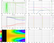
Vertical Listening Impression
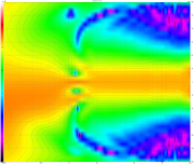
I also noticed performance didn't seem to be degraded very much when listening off vertical axis. I thought I would hear a hole as I moved above 15 degrees but I didn't notice it. The speakers are toed in so maybe that plus reflections filled in the vertical holes. Granted, could just be my imagination getting the best of me again.
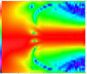
Vertical Standard/Normalized
Decided I preferred a 1,200 Hz crossover over a 1,000 Hz crossover. Compared each using a 444 mm/17.48 center-to-center distance between waveguide and woofer. I now prefer the sound of 1.55 wavelength c-t-c multiplier (286 mm 1.2kHz) over the 1.29 c-t-c spacing (344 mm 1kHz). In the original post (#13,919) I preferred a 1kHz crossover with a 1.29 c-t-c spacing multiplier over the 1.2 c-t-c spacing.
I compared the two crossovers using streaming TV dialogue. 1.2kHz has too much S consonant coloration and 1kHz has too much boom coloration. I chose 1.2kHz because it seems to have less coloration overall. Excess S consonant coloration also makes the TV dialogue easier to understand versus excess boom. I also preferred it with female music vocals. Still not sure I prefer it with deep male vocals or not but home theater application tipped the scales for now.
I decided to try 1.2kHz because it gave the best results when using a linear phase brickwall filter. I don't know if that is recommended practice on where to located a crossover or not.

Vertical Listening Impression
I also noticed performance didn't seem to be degraded very much when listening off vertical axis. I thought I would hear a hole as I moved above 15 degrees but I didn't notice it. The speakers are toed in so maybe that plus reflections filled in the vertical holes. Granted, could just be my imagination getting the best of me again.
Vertical Standard/Normalized


Last edited:
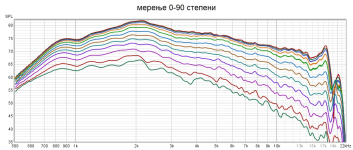
This evening my friend Jokerbre and i measured Peerless DFM2535R00-08 on Mabat's ST260 waveguide.
Measurements are done from 1m distance with calibrated Behringer ECM8000, Steinberg UR12 and gate frequency of 4.4ms so enough to capture trends of this waveguide. What is shown here are measurents 0-90 degrees with ≈7.5 deg increments in between. Since i did not calibrate REW and my mic for loudness, SPL levels shown aren't representative of actual SPL level. Off axis measurements 60 degrees and up are smoothed 1/48 to avoid "hair" at higher frequencies.
0-90 degrees
View attachment 971007
0-45 degress
View attachment 971008
45-90 degrees
View attachment 971009
75dB vs 85dB loudness
View attachment 971010
measurement on axis (red) and averaged 0-90 degrees (purple)
View attachment 971013
printed waveguide
View attachment 971012 View attachment 971011
I must say that i've never seen better and more extended frequency response from a smaller waveguide and a cheaper compression driver.
Just circling back on this- great measurements @Zvu
Here's my Tymphany DFM-2335R00-08 in the SB Audience H250 horn in 10 degree steps, driven with 1V, measured at 1m. 4ms window.
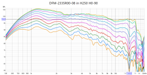
Clearly @mabat ST260 horn is nice improvement over something off the shelf.
Last edited:
A lot of great work here. I still need to go through it, when I have the time...
In the meantime, I'm finishing a new kit (3D print friendly) -


It has a new driver mounting, utilizing the space around the LF-extension duct.
The whole body can then be easily clamped to the rest of a construction -


In the meantime, I'm finishing a new kit (3D print friendly) -
It has a new driver mounting, utilizing the space around the LF-extension duct.
The whole body can then be easily clamped to the rest of a construction -
Last edited:
Has anyone developed a waveguide for the SB Audience 65CDN-T yet? Or the Textreme FaitalPro 1460?
No one gave you an answer yet so I'll take a crack at it. I'm not sure you need to design a waveguide for a specific compression driver. At least, I wouldn't. Instead, I'd design an internal ring to fit inside the throat of the compression driver down to the phase plug exit. The internal ring would then fit to an LF extension duct. I can't think of a reason not include the LF extension - for home HiFi - but I'm not an expert so maybe there are reasons you wouldn't want one.
The internal ring and LF-extension duct attach to ANY waveguide designed for an enclosure (OSSE) or free standing (R-OSSE). I need to redesign my 3D printer files so I can easily detach my waveguides from an LF-extension, which will allow me to swap out waveguides optimized for different goals. So it's a three piece system. 1) Internal Ring, 2) LF-extension duct, 3) waveguide. Waveguides take the most time to print so it's nice to just change the LF-extension and Internal Ring.
Hope that helps.
Thank you for the offer! I don't know anything about the internal ring and extension duct, I assume this is being used successfully in the designs in this thread? I assume one would want to match the exit angle of the driver in question, I don't have that info at this time though.
My use would crossing to a 12" woofer at 1000-1200hz.
My use would crossing to a 12" woofer at 1000-1200hz.
The internal ring is a tweak to extend the waveguide all the way to the compression chamber, skipping the conical section and its specific exit angle or rather supplementing it with a filler insert that reaches into the compression driver, beyond the bug screen. This way, the wavefront does not change until the actual wavefront throat.
The extension duct has been a more recent innovation introduced by Marcel. It appears that a straight or slightly conical tube of several centimeters length supports the loading of the lower passband of a waveguide, compared to the same waveguide without such a duct.
As the exit wavefront of any compression driver approximates a flat disc, as opposed to a dome tweeter, it is not strictly necessary to optimize a waveguide for a certain compression driver, though it could probably be done if you wanted to consider the impedance of the compression driver and subsequently how even an SPL curve the waveguide produces.
Last edited:
Post #13,925 shows an LF-extension. An internal ring would continue that from the CD surface down to the phase plug exit. But it could turn into a straight duct at some point. It wouldn't need to have the same angle. You can even make it smaller than the phase plug exit but you start to trade off SPL when you do that.
Combining an extension duct with an internal ring really seems the way to go (an example can be seen here: #13,746), that's also where I tend to shift with my designs. It's always best to start any waveguide at the smallest diameter possible, which happens to be a phase plug exit. It's important to stress that the LF extension per se virtually doesn't affect directivity (referenced at its exit diameter). The ring improves it.
Last edited:
For experiments with different horns, it can be prepared this way, so the base part is printed only once.
(Either hexagonal-head bolts or nuts can be used.)


I'm actually thinking about making the input diameter e.g. 20 mm and then use ring adapters for different drivers (from their phase plugs).
(Either hexagonal-head bolts or nuts can be used.)
I'm actually thinking about making the input diameter e.g. 20 mm and then use ring adapters for different drivers (from their phase plugs).
Is there something that speaks against a straight, non-conical duct? I am interested in a 20 mm throat diameter.
Without elaborate model of a particular driver, which we don't have, it's hard to say. Straight duct will tend to create a higher-Q resonace (theoretically stronger FR ripple), compared to conical, but without the model it's impossible to predict the consequences with any accuracy. This is still empirical.
I assume an increase in FR ripple also has increased HOM? If that is correct, how are these measuring with and without the extension?
I would expect "more ripple" based on the simulated throat impedance being more wavy, but as we've seen, this is almost useless without a complete model of a driver - there must be something with the real drivers that makes these ripple not at all obvious in a measured SPL response.
A result even with a rudimentary extension can still look like this - https://www.diyaudio.com/community/...-design-the-easy-way-ath4.338806/post-7454567
(BTW, the strongest ripple should be in the midrange, where I wouldn't expect HOMs to any significant level - that's really more a HF phenomenon.)
Last edited:
At high frequencies, the shape of the boundary at the end of the extension is not changed compared to a regular throat. My understanding is that there will be no more HOMs, compared to a regular throat with no extension preceding it. At the end of the extension the wavefront should be in no worse condition than what is otherwise radiated directly from the driver (if not better, but that's just my conjecture).
Anyway, the extension duct can be always filled with a sparse open-cell foam. So there's a chance that those HOMs radiated from the driver will get attenuated even before they reach the waveguide. I tend to think of the extension as a kind of a zero-mode filter (zero mode being a spherical wave in a case of a conical duct).
Anyway, the extension duct can be always filled with a sparse open-cell foam. So there's a chance that those HOMs radiated from the driver will get attenuated even before they reach the waveguide. I tend to think of the extension as a kind of a zero-mode filter (zero mode being a spherical wave in a case of a conical duct).
Last edited:
- Home
- Loudspeakers
- Multi-Way
- Acoustic Horn Design – The Easy Way (Ath4)