For the hemispherical on-wall enclosure to equal a free space sphere, the driver has to be flush against the wall, firing up or down. If you absorb some of the wall reflection then you can break the symmetry and approximate an upward firing tweeter-mid pair. This can sound pretty decent.
I've been contemplating on wall speakers and am leaning towards something like a Linkwitx Pluto/LXMini where a woofer cylinder is flush with the wall and the tweeter is in a wide shallow (ATH inspired) waveguide that is blended in smoothly to the wall. If you use two woofer pipes you can adjust horizontal directivity by changing their spacing. Basically an on-wall optimised version of this design instead of a free-space optimised version.
I think it's better to allow a small amount of diffraction from the tweeter off of the woofer enclosure in order to have the tweeter more flush with the wall and avoid diffraction at the tweeter WG/wall interface.

Spotted the 1" Cmp35_vPA from Kartesian Acoustic
https://www.kartesian-acoustic.com/copie-de-cmp25-vhp
Anyone used this driver?

https://www.kartesian-acoustic.com/copie-de-cmp25-vhp
Anyone used this driver?
I strongly doubt that.
Welp, I forgot to take into account that source gets reflected too, so instead of a monopole on a spherical source we get a (most porbably useless) bipole.And perhaps show in simulation comparing the two for verification of a tool... or thesis...
//
This is a bit off topic - but in the spirit of controlled directivity.
A lot of very good horns are being designed here, but there
are not that many cabinets that can match their directivity.
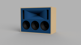
I'm flirting with the idea of using a 3x10" drivers cabinet, lowpassing the side ones to 250 Hz.
So at frequencies above 250 Hz the directivity approaches a 10" on a large baffle.
And for frequencies below 250 Hz the directivity transitions into that of a virtual 32" woofer. (in the horizontal axis)
Now the plot can be made prettier by dialing the lowpass frequency and slope and perhaps adding some delay to the mid woofer.
I'm aware that Cardioid and Dipole configurations can provide directivity, but how about if the speakers are mounted in the wall?
Do large studio monitor manufacturers care about directivity?
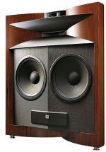
How do you explain this speaker? (not going to mention the version with tweeters on both sides)

A lot of very good horns are being designed here, but there
are not that many cabinets that can match their directivity.
I'm flirting with the idea of using a 3x10" drivers cabinet, lowpassing the side ones to 250 Hz.
So at frequencies above 250 Hz the directivity approaches a 10" on a large baffle.
And for frequencies below 250 Hz the directivity transitions into that of a virtual 32" woofer. (in the horizontal axis)
Now the plot can be made prettier by dialing the lowpass frequency and slope and perhaps adding some delay to the mid woofer.
I'm aware that Cardioid and Dipole configurations can provide directivity, but how about if the speakers are mounted in the wall?
Do large studio monitor manufacturers care about directivity?
How do you explain this speaker? (not going to mention the version with tweeters on both sides)
Attachments
Last edited:
Can't you use a cardioid configuration with drivers on the front baffle? A quickly tried in vCad, Z-shifted them, and it seems to work. You would need DSP for timing and SPL.I'm aware that Cardioid and Dipole configurations can provide directivity, but how about if the speakers are mounted in the wall?
Also, in this presentation of the cardioid GGNTKT M1 by Roland Schäfer
Last edited:
Small update on my project.
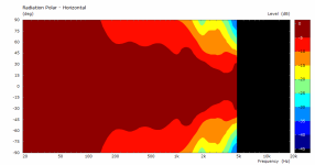
Quite wobbly above 10k.
HF10AK no EQ
900Hz high pass 22uF / 8ohm
9dB/8ohm resistor pad
0 to 110 degrees
500mm radius from baffle front face


Quite wobbly above 10k.
HF10AK no EQ
900Hz high pass 22uF / 8ohm
9dB/8ohm resistor pad
0 to 110 degrees
500mm radius from baffle front face


The HF10AK is quite wobblySmall update on my project.
Quite wobbly above 10k.
HF10AK no EQ
900Hz high pass 22uF / 8ohm
9dB/8ohm resistor pad
0 to 110 degrees
500mm radius from baffle front face
View attachment 1226658 View attachment 1226663
That's a nice result, but requires active EQ for best performance (not a problem IMO). What's the dimensions of your WG?Small update on my project.
Quite wobbly above 10k.
HF10AK no EQ
900Hz high pass 22uF / 8ohm
9dB/8ohm resistor pad
0 to 110 degrees
500mm radius from baffle front face
View attachment 1226658 View attachment 1226663
A note on the measurement setup: You are not rotating around the acoustic centre, which is moving the curves artificially close together. Try using the outlet from the CD as the centrum point.
/onni
Wow, DI is perfect. What was your final solution to counteract waist-banding effect at the lower end of the passband of the waveguide?CTA-2034-A defaults for DI.
Re-measured at 280mm radius, 10 degree increments, from HF10AK exit.
Applied basic XO suggestion from @tmuikku that has potential to resolve the 2k issue.
Far from finished...


Applied basic XO suggestion from @tmuikku that has potential to resolve the 2k issue.
Far from finished...
Last edited:
The 2k "issue" is no issue with proper EQ or? - the dip seems mostly directivity independent so it will just straiten out nicely.
//
//
Yeah it's no problem with DSP, but with passives a bit tricky. Although it's not very audible as such, it is possible to mitigate it by the above filter. However, I do not know if it works any better in system context than a filter that leaves the dip. Of course, chasing for perfect graphs it's no no, although only ~3db or so.
Placing axis of rotation at waveguide mouth leads to a measurement error, as shown/explained here https://www.diyaudio.com/community/threads/my-first-crossover-2-way-w-vituixcad.400995/post-7400529Small update on my project.
Quite wobbly above 10k.
HF10AK no EQ
900Hz high pass 22uF / 8ohm
9dB/8ohm resistor pad
0 to 110 degrees
500mm radius from baffle front face
View attachment 1226658 View attachment 1226663
@VoxCelestial - changed to measuring by rotating at CD exit, 280mm.
Huge thanks to @mabat for ATH4 !
Power & DI

Horizontal, 10deg, 280mm from CD exit
.png")
Vertical, 10deg, 280mm from CD exit
.png")
Huge thanks to @mabat for ATH4 !
Power & DI
Horizontal, 10deg, 280mm from CD exit
Vertical, 10deg, 280mm from CD exit
Simulated an enclosure using ATH to match with a R-OSSE waveguide. I've been trying to understand directivity matching. My next step is to print a higher DI waveguide to compare against the flatter DI R-OSSE. (Thanks, Mabat, I sent you a donation at the beginning of October. Your software has been a tremendous learning tool. Paypal didn't have a spot for a comment otherwise I would have thanked you there.)


Subjective listening impressions
Didn't how to optimize an enclosure for directivity matching so I gambled on prioritizing horizontal directivity over vertical. The shaped enclosure was quite a bit more difficult to cut than a simple cube box and I spent a lot of time during construction wondering whether it was going to be able to notice a difference or not. After listening a few days the biggest thing I noticed was TV/movie dialogue is more intelligible when listening is limited to two channel stereo. Using a center channel always sounded more intelligible but when the TV source was only available in two channels the shaped enclosure worked better than the cube in terms of intelligibility. However, that could be my imagination so don't assign too much weight to my subjective opinion. For whatever reason, it is easier - for me - to understand the actors with the shaped enclosures when restricted to two-channels without the center vs the cube enclosure.
In addition, I noticed the speaker seems to sound better when the waveguide is further from the enclosure. I used a 1.2 wavelength center-to-center distance then adjusted crossover frequency to move the waveguide closer to or further from the woofer. I don't know the right words to describe it so I'll say the speaker sounds "cleaner" when I move the waveguide further away from the enclosure by using a lower frequency crossover or pushing a little past the 1.2 wavelength c-to-c distance for a given crossover frequency. IMO, increasing the c-to-c from 412 mm to 444 mm (arbitrary choice) improved the sound by making it cleaner. However, I never tried moving the waveguide further forward on the Z-axis while using a closer center-to-center distance on the Y-axis. Also, all this could be in my imagination because I'm the only one who listened and made comparisons between changes.
Crossover: LR48 1,000Hz (344 mm full wavelength)
Distance between bottom of waveguide and top of enclosure: apprx 171 mm/6.75 inches
Center-to-center distance between waveguide and woofer: 412 mm/16.2 inches (1,000Hz 344 mm x 1.2 = 412 mm) - although, I currently have it at 444 mm because I think it sounds better.
Construction note: I used Premcore-Plus plywood. Noticeably lighter weight than typical cabinet grade plywood. Has some gaps in the layers so not a perfect exposed edge like some higher grade plywoods. On the other hand, if I wanted a lighter weight cabinet for a larger portable enclosure this would be good stuff. https://www.canusawood.com/premcore-plus
Enclosure Simulations
Standard Cube Simulation (228 mm, 9 inch cube):


Shaped Enclosure Simulation (260 mm wide, 260 mm tall, 240 mm deep) : Horizontal/Vertical


.png")
REW Measurements (shaped enclosure)
Ground Plane: Horizontal/Vertical


Elevated 1.4 meters (4'7") from center of woofer to ground on a tripod and turntable: Horizontal/Vertical


VituixCAD: Simulations vs REW Measurements
I've been struggling to make my measurements accurate and I noticed it helps a lot to be able to compare REW measurements against simulations. My waveguide measurements are wrong because I measured at the front of the waveguide rather than the acoustic center. As a result the measurements show around a 1 dB wider directivity index compared to the simulations. I chose to stick with measuring from the front of the waveguide for now to make XYZ adjustments in VituixCAD easier. But it's obviously not the correct way to do it.
Enclosure with Dayton DC-200-8 woofer and R-OSSE with B&C DE111 compression driver. Compression driver had a 47uf capacitor inline high pass during measurement.


Linkwitz-Riley 48 crossover with VituixCAD generated transfer WAV files to equalize both driver flat before crossover application.

VituixCAD Simulation vs REW measurements. You can see how measuring from the front of the waveguide widened the directivity index apprx 1 dB compared to the simulation.


I attached a zip with the enclosure and waveguide ATH configuration files.
Subjective listening impressions
Didn't how to optimize an enclosure for directivity matching so I gambled on prioritizing horizontal directivity over vertical. The shaped enclosure was quite a bit more difficult to cut than a simple cube box and I spent a lot of time during construction wondering whether it was going to be able to notice a difference or not. After listening a few days the biggest thing I noticed was TV/movie dialogue is more intelligible when listening is limited to two channel stereo. Using a center channel always sounded more intelligible but when the TV source was only available in two channels the shaped enclosure worked better than the cube in terms of intelligibility. However, that could be my imagination so don't assign too much weight to my subjective opinion. For whatever reason, it is easier - for me - to understand the actors with the shaped enclosures when restricted to two-channels without the center vs the cube enclosure.
In addition, I noticed the speaker seems to sound better when the waveguide is further from the enclosure. I used a 1.2 wavelength center-to-center distance then adjusted crossover frequency to move the waveguide closer to or further from the woofer. I don't know the right words to describe it so I'll say the speaker sounds "cleaner" when I move the waveguide further away from the enclosure by using a lower frequency crossover or pushing a little past the 1.2 wavelength c-to-c distance for a given crossover frequency. IMO, increasing the c-to-c from 412 mm to 444 mm (arbitrary choice) improved the sound by making it cleaner. However, I never tried moving the waveguide further forward on the Z-axis while using a closer center-to-center distance on the Y-axis. Also, all this could be in my imagination because I'm the only one who listened and made comparisons between changes.
Crossover: LR48 1,000Hz (344 mm full wavelength)
Distance between bottom of waveguide and top of enclosure: apprx 171 mm/6.75 inches
Center-to-center distance between waveguide and woofer: 412 mm/16.2 inches (1,000Hz 344 mm x 1.2 = 412 mm) - although, I currently have it at 444 mm because I think it sounds better.
Construction note: I used Premcore-Plus plywood. Noticeably lighter weight than typical cabinet grade plywood. Has some gaps in the layers so not a perfect exposed edge like some higher grade plywoods. On the other hand, if I wanted a lighter weight cabinet for a larger portable enclosure this would be good stuff. https://www.canusawood.com/premcore-plus
Enclosure Simulations
Standard Cube Simulation (228 mm, 9 inch cube):
Shaped Enclosure Simulation (260 mm wide, 260 mm tall, 240 mm deep) : Horizontal/Vertical
REW Measurements (shaped enclosure)
Ground Plane: Horizontal/Vertical
Elevated 1.4 meters (4'7") from center of woofer to ground on a tripod and turntable: Horizontal/Vertical
VituixCAD: Simulations vs REW Measurements
I've been struggling to make my measurements accurate and I noticed it helps a lot to be able to compare REW measurements against simulations. My waveguide measurements are wrong because I measured at the front of the waveguide rather than the acoustic center. As a result the measurements show around a 1 dB wider directivity index compared to the simulations. I chose to stick with measuring from the front of the waveguide for now to make XYZ adjustments in VituixCAD easier. But it's obviously not the correct way to do it.
Enclosure with Dayton DC-200-8 woofer and R-OSSE with B&C DE111 compression driver. Compression driver had a 47uf capacitor inline high pass during measurement.
Linkwitz-Riley 48 crossover with VituixCAD generated transfer WAV files to equalize both driver flat before crossover application.
VituixCAD Simulation vs REW measurements. You can see how measuring from the front of the waveguide widened the directivity index apprx 1 dB compared to the simulation.
I attached a zip with the enclosure and waveguide ATH configuration files.
- Home
- Loudspeakers
- Multi-Way
- Acoustic Horn Design – The Easy Way (Ath4)