My statement was wrong. Original simulations were at 2 meters but my measurements were at 1 meter so I went back and recreated the simulations at 1 meter with the axis at the front of the waveguide. I thought that would make the simulation match the real world measurements but it didn't. I don't know why my waveguide measurement is 1 dB lower on the Directivity Index than the simulation. TBD
I may have discovered why my REW measured Directivity Index in VituixCAD did not match my simulated directivity index from ABEC. VituixCAD instructions say to use 5 degree increments when measuring a horn. The first time I measured my horn I followed the instructions but I used a Dayton USB microphone. Months later I bought an analog microphone and measured the same waveguide but using 10 degree increments. The 5 degree measurement matches the simulatiuon from ABEC. Now I need to start looking for a good day to go back out and measure in 5 degree increments with the analog microphone to confirm.
ABEC Sim/ 5 degree measurements/ 10 degree measurements


Ive recently printed parts for Mabats new Exar-400-25. Thisfar im in sanding process with spray filler.
Im impressed about design of all parts and how they fit together. Its cool that you can make this big horn with 250mm bed printer. Theres some sanding and work for needle files but thats normal for 3d-printed projects. I will try to cross them with RCF L15-541 woofers (or 2226H, already have them also)
1" drivers that can be tried are DE250, DFM2535 and some vintage RCF´s. Will post more later but there will be slight pause due to work.
Attachments
Last edited:
Update:
Although the horn looks great in itself, it appeared that there is room for improvement in the settings of my printer: the petals are not completely level with each other all the way, but there is a small gap in the joints of the outer circumference. I will solve the problem with 2k putty regarding the gaps in the outer ring. I recommend others who may be starting this project to print only two petals first and study their placement in relation to each other. My enthusiasm to print everything at once made it possible to practice with the putty now, doh 😊
Thanks for Mabat for guiding me to better finish. Parts should fit even better when all settings and correct filament is used.
I have the parts all printed but not assembled yet. Tried a quick dry run and it looked pretty good so far. It's not always easy to print construction parts with high dimensional accuracy. A lot of things can have an effect. Well, that's just the 3D printing. With BambuLab X1C I'd expect perfect results however. I'd bet on the filament used - it has probably warped a bit due to temperature changes. You wouldn't notice it on a sculpture but here it obviously stands out. Perhaps try to heat up the bed and reduce the nozzle temperature as feasible. Hard to say, too many variables.
Last edited:
BTW, this waveguide should be very similar to the hexagonal prototype I used: #13,730
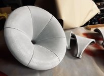
It's just a bit smaller and the mouth is circular (which is more or less aesthetics, but maybe it has a slight edge over the hex).
The interior is still hexagonal.
- I want mine to have a metal look, so I'll use an epoxy coating with brass powder (or maybe some other mixture). Slightly battered look is fine - that's how it typically turns out anyway 🙂
Last edited:
"I want mine to have a metal look, so I'll use an epoxy coating with brass powder (or maybe some other mixture). Slightly battered look is fine - that's how it typically turns out anyway"
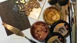
Im looking for similar finish with some patina. One way to achieve it:
--> After sanding and priming, paint to black.
--> Wipe Inka Gold etc metallic wax to whole piece
--> rub with microfiber cloth or sponge that is moist with turpentine or naptha
Im looking for similar finish with some patina. One way to achieve it:
--> After sanding and priming, paint to black.
--> Wipe Inka Gold etc metallic wax to whole piece
--> rub with microfiber cloth or sponge that is moist with turpentine or naptha
Attachments
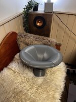
I like this part the most. It's when it suddenly turns into something nice (and almost real)...
Last edited:
Im impressed about design of all parts and how they fit together. Its cool that you can make this big horn with 250mm bed printer. Theres some sanding and work for needle files but thats normal for 3d-printed projects.
Despite CLEARLY imperfect 3D prints my waveguides still measured just like the simulations. I had some gaps I covered with tape and the outer edges of the waveguide are slightly but visibly warped. I did have problems importing my measurements into VituixCAD but that wasn't a waveguide problem it was a user problem. For putting a system together to see how it sounds/measures I wouldn't worry about imperfect 3D prints. Save the craftsmanship effort for cosmetics in your final build.
Last edited:
I wanted the whole WG body to be easily clamped to the rest of a construction.
The next version will be inside out, i.e. the outer shell will be fixed (connected directly to some holder or stand)...
The downside being there will be one more detachable interface, probably not that critical in the end.


The next version will be inside out, i.e. the outer shell will be fixed (connected directly to some holder or stand)...
The downside being there will be one more detachable interface, probably not that critical in the end.
Last edited:
Does that one have better rear waveguide performance? I'm not sure what to call it when diffraction from the rear of the freestanding waveguide degrades forward frequency response.
Working on the mounting options, I've finally found something pretty universal and adaptable.


Another finishing option, could be quite sleek-


BTW, this is including a throat ring for the D2500TiNd. Different drivers will have different flange.
The diameter of the base part is 20 mm.


BTW, this is including a throat ring for the D2500TiNd. Different drivers will have different flange.
The diameter of the base part is 20 mm.
Last edited:
There's always something else to try...
This is an uneven distribution of the petal angles (could be completely random, any number of segments).
Unfortunately I can't simulate this easily so it would need to be tested in real. The idea of course would be to further spread all the higher-order stuff in space and time.


This is an uneven distribution of the petal angles (could be completely random, any number of segments).
Unfortunately I can't simulate this easily so it would need to be tested in real. The idea of course would be to further spread all the higher-order stuff in space and time.
Last edited:
There's always something else to try...
This is an uneven distribution of the petal angles (could be completely random, any number of segments).
Unfortunately I can't simulate this easily so it would need to be tested in real. The idea of course would be to further spread all the higher-order stuff in space and time.
View attachment 1236138 View attachment 1236139
It's not the same thing, but your software can sim an odd number of petals. Took me a while to figure it out, I used that to sim triangular waveguides:
https://www.diyaudio.com/community/threads/triangular-waveguides.403212/
- Home
- Loudspeakers
- Multi-Way
- Acoustic Horn Design – The Easy Way (Ath4)