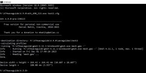
This is what my console looks like when I run it. The files in the attached ZIP should be in your c:\Horns\test2\ folder. Page 6 of the ATH user manual (also attached) explains the "%f -" suffix. Did you include a space between the f and the dash?
Attachments
Thanks @CinnamonRolls
I noticed you were running 4.9.0. I remembered seeing this on the ATH4 website...
The last released package: Ath 4.8.2 with a User Guide; the latest build (recommended).
I clicked on build and downloaded a new ath.exe. Replaced the one that came in the Ath 4.8.2 package with the new one, and it worked!
Dumb mistake.
Got an STL file and no errors with the dash. Will continue my journey.
Thanks again!

A short summary of where we are now, regarding the horn design: http://www.at-horns.eu/exar-story.html
Im having some issues. I only get .geo files as output and no stl files. Converting them manually in gmsh gets me an stl but then for example my 3d print slicer doesnt recognise the file. Has anybody had the same issue?
I don't think you can go straight to a slicer because the generated STL is only a two dimensional surface. You need to convert it into a 3D model first using a program such as Microsoft 3D Builder.
I had the same problem, no STL. Did you follow what I did a few posts up?Im having some issues. I only get .geo files as output and no stl files. Converting them manually in gmsh gets me an stl but then for example my 3d print slicer doesnt recognise the file. Has anybody had the same issue?
The STL produced by Ath is not very useful for anything else than a quick visual check of the created shape. For CAD, there are other ways, as was mentioned. With axisymmetric shapes it's very simple (#5,083). Not quite so with the non-axisymmetric and I'm not sure about the level of documentation provided, here or in the User Guide. Unfortunately, I just can't spend time with this anymore...
Did anyone try a PLA-LW (foaming) filament? It seems it could be an interesting option for the petals - lightweight and better damped.
For a construction like this -

For a construction like this -
I'm already assembling a kit but still only a regular PLA. I'm sure it could be better.

If damping is what you need - try the flexible petg from SpectrumDid anyone try a PLA-LW (foaming) filament? It seems it could be an interesting option for the petals - lightweight and better damped.
For a construction like this -
View attachment 1242712
https://spectrumfilaments.com/en/filament/pet-g-fx120/
These special filaments are usually quite expensive. Would car-audio Dynamat etc materials attached to backside (cutted in nice shape and painted after attaching) work?
PLA-LW wouldn't be that expensive if it worked as advertized, i.e. being able to print the same volume with half the density - that would get you to roughly the same price as for a spool of some "ordinary" material. The problem is, of course, that such exotic materials typically take quite a lot of experimenting prior to any final work... That's why I ask 🙂 Intuitively, I like the idea of the lightweight cell structure (for the petals)...
I'm also thinking about adding some "dampers" to the back side of the waveguide (damped rods or something - it must look good). I have no idea about the effectiveness of the car-audio damping plates.
I'm also thinking about adding some "dampers" to the back side of the waveguide (damped rods or something - it must look good). I have no idea about the effectiveness of the car-audio damping plates.
Last edited:
BTW, I've just noticed a new 3D printer by TwoTrees: https://www.twotrees3dofficial.com/products/sk1-corexy-3d-printer-twotrees
It looks incredible for that price. I only wish I could start with something like that a few years ago...
It looks incredible for that price. I only wish I could start with something like that a few years ago...
Last edited:
Nice design. I like the linear rails all round. Has the same build volume as Bambu Core XYs (pity it's not bigger). Not much information about build materials. Will check out reviews. Exciting time for 3D printing.BTW, I've just noticed a new 3D printer by TwoTrees: https://www.twotrees3dofficial.com/products/sk1-corexy-3d-printer-twotrees
It looks incredible for that price. I only wish I could start with something like that a few years ago...
What models do you mean? Some of the EXAR waveguides? I can provide such models (not necessarily the same as the 3D print kits) - if you are interested, please write me a message. I guess that for CNCing from wood, round (axisymmetric) versions would be more appropriate... (?)If there are solid models, I can cnc them out of wood and test them.
I should be able to measure these waveguides soon myself, I have them almost finished. The EXAR 400-25 is virtually the same device as was experimented with originally, but the 340-20 is a new one.
Last edited:
As for the lightweight (foaming) filaments, there's also a Czech company 3DLabPrint making them - https://3dlabprint.com/product-category/3d-filament/
Currently $35 for a 1 kg spool. I'm going to give it a try.
Currently $35 for a 1 kg spool. I'm going to give it a try.
Last edited:
@mboxler clued me in to a new build of ATH so I tried it out. Version 231015 automatically adds the "Direction=z" to the Solving.txt file for you when using custom driver diaphragms formed using Source.Contours when you set Source.Velocity = 2 (move diaphragm in axial direction). Thanks, mabat! That was a big help because I'd always forget to add it when doing multiple runs to get my diaphragm measurements correct. Attached a zip of a configuration file I made for a Sica coaxial driver as an example. @vineethkumar01, this is the same driver you used in your coax cardioid build, Sica 5,5 C 1,5 CP. I bought one after I saw how successful your project was.

For anyone who wants to use the two config files I recommend the latest ATH build, obviously. Also, I commented out some Source.Contours statements that are more detailed around the tweeter but don't improve the simulation. Instead, I added simplified contours to reduce processing time. Source.Contours resolution is set too high in the tweeter file for reasonable processing times so you will want to decrease that. Two attached configuration examples: 1) tweeter file hides waveguide behind a surface mounted driver. 2) woofer file places a waveguide over woofer starting above the second surround.
Tweeter elements turned on (woofer off): Waveguide hidden, driver surface mounted.

Woofer elements turned on (tweeter off): Simple waveguide w/ driver recessed into enclosure.

For anyone who wants to use the two config files I recommend the latest ATH build, obviously. Also, I commented out some Source.Contours statements that are more detailed around the tweeter but don't improve the simulation. Instead, I added simplified contours to reduce processing time. Source.Contours resolution is set too high in the tweeter file for reasonable processing times so you will want to decrease that. Two attached configuration examples: 1) tweeter file hides waveguide behind a surface mounted driver. 2) woofer file places a waveguide over woofer starting above the second surround.
Tweeter elements turned on (woofer off): Waveguide hidden, driver surface mounted.
Woofer elements turned on (tweeter off): Simple waveguide w/ driver recessed into enclosure.
Attachments
I should be able to measure these waveguides soon myself, I have them almost finished. The EXAR 400-25 is virtually the same device as was experimented with originally, but the 340-20 is a new one.
Hi Marcel,
I take it that the graphs here represent the sims?
http://www.at-horns.eu/exar.html
I’m looking forward to see how the measurements match the simulation for both the EXAR 400-25 and 340-20.
Will you be using the DFM2335?
Please let us know how we can support your work.
Yes, and as we already know, the sims match the measurements almost perfectly: https://www.diyaudio.com/community/...-design-the-easy-way-ath4.338806/post-7419720I take it that the graphs here represent the sims?
The EXAR 400-25 should quite closely match the original measurements shown here: https://at-horns.eu/exar-story.html
It's just a bit smaller and maybe free of some slight residues of mouth diffraction.
That's regarding the radiation pattern (directivity, diffrations, etc.). As for an absolute SPL for a particular driver, that's what still needs to be tested, especially for the 340-20.
Last edited:
- Home
- Loudspeakers
- Multi-Way
- Acoustic Horn Design – The Easy Way (Ath4)