I suppose the next question might be “Does Frank’s circuit use the op amps at the Muses output in the signal path or not?”
No idea…all this is news to me and over my head.
I leave data sheets and circuit design to smart people like NP, ZM and Frank. 😉
No idea…all this is news to me and over my head.
I leave data sheets and circuit design to smart people like NP, ZM and Frank. 😉
From studying he pictures of Franks boards and a little email discussion with him I am 99.2% sure there is no opamp in the IP muses volume from him. 😎 A major reason to be excited!

there are no AMP OP inside of the MUSES .
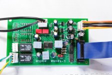
This is the kit that I built for my little ACP+ from PASS
https://www.diyaudio.com/community/threads/my-muses-72320-volume-control.400831/
This is the kit that I built for my little ACP+ from PASS
https://www.diyaudio.com/community/threads/my-muses-72320-volume-control.400831/
Attachments
absolutely no need for internal OP, when Muse volume applied in context of IPre
Thanks, ZM. It is very reassuring that opamps are not needed. We don't want them opamps in the signal path!
Just to clarify what I meant (for the benefit of others): The datasheet suggests using opamps outside the Muses chip. There are no opamps inside the chip.
there are no AMP OP inside of the MUSES .
This is the kit that I built for my little ACP+ from PASS
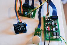
Thank you for showing your Muses attenuator, lalaina. That is a very nice implementation. Well done! Using a Pic MCU. Interesting!
See my previous post about the Op Amp not being inside the Muses chip.
What do you mean by "isolated digital and analog section"? How did you achieve that?
I don´t use an Op Amp in the IP solution.
There were/are some solutions that can be found on my website in which an op amp was used. One reason is that the Muses chip can drive an op amp directly to create gain.
In another (completely new solution), a BUF634A is connected downstream to greatly reduce the output impedance.
Neither is necessary with the Iron Pre. So no op amp. This should also be visible in the pictures on the IP website.
@Skylar88 "And finally, are there any happy users of Muses coupled to IronPre out there, or is Muses attenuation + IP still experimental?"
The Muses chip should not care whether it is used in front of the IP or a Class A tube amplifier. I can only report that most of my customers almost always spoke of a clear improvement in sound. At least when they use the chip to replace an existing potentiometer.
The Muses chip should not care whether it is used in front of the IP or a Class A tube amplifier. I can only report that most of my customers almost always spoke of a clear improvement in sound. At least when they use the chip to replace an existing potentiometer.
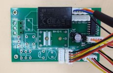
Here are pictures of the MC-board assembled for test purposes. Es wurde nur der 5V MW bestückt, da ich 5V-Relais verwende.
I am still at a training course until next weekend. In the following days, I hope to be able to present the finished solution.
I am still at a training course until next weekend. In the following days, I hope to be able to present the finished solution.
Attachments
Judging by the number of Muses solutions I have seen on the Internet, there must exist quite a lot of knowledge in the community about implementing Muses chips, especially the older 72320 chip. But it also seems like everyone wants to keep their knowledge to themselves – probably in order to sell their ‘unique products’. And that is understandable.
But I think not everyone wants to use the same Oled or LCD screen, or the same microcontroller, or even the same remote. So, I think there is need for a repository of information which is free and open to everyone who wants to build their own Muses attenuator.
In the interest of DIY, would anyone be interested to collaborate with fellow DIYers and share: Microcontroller code, libraries, working schematics, tips, experiences, etc. Voluntarily and free of course.
If there is enough interest, we can start a sub-forum like this Logic Solutions thread. Anyone?
I am sorry that the development is dragging on like this. I actually thought I would be able to announce the completion of the project at the end of last week. Unfortunately, there were problems in the interaction with the port extension and the relay control. I often use this combination, but never had the problem that the ULN2803 could not be driven.
The problem is now solved. A few more resistors ensure the correct switching through.
Unfortunately, I had also forgotten the pull-up resistors for the I2C bus.
The problem is now solved. A few more resistors ensure the correct switching through.
Unfortunately, I had also forgotten the pull-up resistors for the I2C bus.
Additionally, I noticed that there might be a problem with gnd if the balanced solution were to be operated in double-mono setup. This would result in a merging of gnd of both power supplies at the digital isolator. Since this is not desirable, the only solution is a 2nd digital isolator.
I have now modified two circuit boards with which both solutions (balanced and unbalanced) can at least be tested.
However, I don't want to modify each board by hand before I put it into your hands.
I have already designed a new MC board. With it, all variants can be covered. I ordered the boards yesterday.
However, I don't want to modify each board by hand before I put it into your hands.
I have already designed a new MC board. With it, all variants can be covered. I ordered the boards yesterday.
I will carry out the tests in the next 2 to 3 days and then report back.
I know that some DIYer have been waiting longer for the completion. I would like to ask for patience, as I am not satisfied if a solution does not work completely.
I know that some DIYer have been waiting longer for the completion. I would like to ask for patience, as I am not satisfied if a solution does not work completely.
^ Thank you for the update and all the work to bring a fantastic solution.
Frank, we were in touch some years ago when you first started down this road. I never went ahead with that project. I managed to snag one of the last remaining Iron Pre balanced kits recently and, although it’s not in my greedy paws yet as it was sent to a friend’s home in Florida, I’ve started to plan for it. I slogged through all 120+ pages of the Iron Pre Interest thread and made notes and only came upon a reference to you and your contribution yesterday when I got to the link to this thread. As before, I am in awe of how much you get stuffed into a 328P! Kudos.
I am not a trained programmer or EE but like some here I have quite a few years of messing with Arduinos and designing PCBs for my projects (I use Diptrace, which dates me a bit 🙃). i spent a few days rejigging a sketch I’ve been using for Soekris DAC projects to work with the Iron Pre. Then, yesterday, I came across your name here and…. you’ve already elegantly done all the heavy lifting!
But, like all Greedy Boyz, I want it ALL! So I have two requests - a tape monitor option and a simple Display Off remote/rot enc option. And, as your posts today seem to indicate, you are still not quite out of the development stage so I’m hoping it’s not too late to look at my requests.
I know space is tight on your 328P code so would even give up the ‘turn off after ‘x’ seconds’ feature in favour of having the option to simply do it manually if coding space became critical.
I had a quick look on your main site and the pads/header you include before the Muses chip (for a DSP loop) on your Balanced Input boardwould work fine for the Tape Out providing Input 5 (which would be Tape In) could be coded not to be included as a selected source when ‘Tape’ was selected.
It also looks, at a quick glance, that another relay or two would be needed to direct the selected (1 to 4) source to the Muses side of those pads/header when Tape is selected. Or is there a clever way to do it with minimum change to existing boards?
Had another look at the Iron Pre Muses boards. Guess it would need a DPDT Form C relay on the Muses boards, pads for the Tape In RCAs, pads for the unattenuated source signal to Tape Out RCAs and pads for relay power and the unused seventh pin from the relay header (now you know why you put that in, Frank 🙃). And some more coding by Frank. That would effectively make six inputs, including a tape monitor!
Clumsy way would be to have a ‘dirty tape monitor’ by hardwiring the CW and CCW to Tape Out RCAs and put a switch somewhere to interrupt their signal going back into the deck when whichever of the Iron Pre’s Inputs the deck’s Tape Out was plugged into was selected. Ugh!
Clumsy way would be to have a ‘dirty tape monitor’ by hardwiring the CW and CCW to Tape Out RCAs and put a switch somewhere to interrupt their signal going back into the deck when whichever of the Iron Pre’s Inputs the deck’s Tape Out was plugged into was selected. Ugh!
In Frank's defense, I smell requirements creep. Every feature is one more thing to test, one more potential problem, and one more potential delay. I will be very happy with whatever he produces.
If anyone has working Arduino code for any of the the Muses chips, please feel free to share it: Digital Attenuation – Repository & Collaboration thread for DIY
Code for other MCUs is welcome too.
Code for other MCUs is welcome too.
@ARGOS, Thank you.😉
@derekr, 😎We'll have to go into that again. Maybe not in this thread, but through personal contact. However, you are at the back of the queue with your wishes.
Whereby it is the case that this software is constantly being changed in one function or another.
At the moment, it is more important to get the basic software running properly first.
- Home
- Amplifiers
- Pass Labs
- Logic Solutions for Iron Pre Kits