@EL8
I'm not an expert on the Ayumi model but it's possible that the Ayumi 6SH7 model in post # 3695 might work with Pspice if you simply change the pin order in the .SUBCKT line to A G1 K G2. The parameter formulas refer to the pins by name and don't seem to care about their position in the .SUBCKT definition, although a schematic capture definitely will care about the pin order. You might try this and see if it works. Nothing ventured, nothing gained, as the saying goes.
I'm not an expert on the Ayumi model but it's possible that the Ayumi 6SH7 model in post # 3695 might work with Pspice if you simply change the pin order in the .SUBCKT line to A G1 K G2. The parameter formulas refer to the pins by name and don't seem to care about their position in the .SUBCKT definition, although a schematic capture definitely will care about the pin order. You might try this and see if it works. Nothing ventured, nothing gained, as the saying goes.
Yes, agree.Yes, is a pity, he is a very helpful guy, lots of the models I use came from him.
" lots of the models I use came from him." me too😉
@Ray Waters
Hi Ray, Thanks for your advice.
I tried you way but it didn't work, I think it's about the format, it's ok if you use paint_kip.jar to make it, just like the sticker below.
Hi Ray, Thanks for your advice.
I tried you way but it didn't work, I think it's about the format, it's ok if you use paint_kip.jar to make it, just like the sticker below.
Attachments
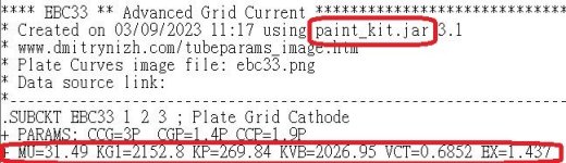
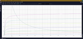
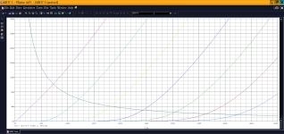
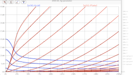
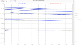
I'm learning to use paint_kip.jar, this is a very rough model, just for reference.
** 6SH7 ****************************************
* .SUBCKT 6SH7 P G2 G K ; LTSpice tetrode.asy pinout
.SUBCKT 6SH7 P G K G2 ; Koren Pentode Pspice pinout
RE1 7 0 1G ; DUMMY SO NODE 7 HAS 2 CONNECTIONS
E1 7 0 VALUE= ; E1 BREAKS UP LONG EQUATION FOR G1.
+{V(G2,K)/KP*LOG(1+EXP((1/MU+(VCT+V(G,K))/SQRT(KVB+V(G2,K)*V(G2,K)))*KP))}
RE2 6 0 1G ; DUMMY SO NODE 6 HAS 2 CONNECTIONS
E2 6 0 VALUE={(PWR(V(7),EX)+PWRS(V(7),EX))} ; Kg1 times KIT current
G1 P K VALUE={V(6)/KG1*ATAN((V(P,K)+KNEX)/KNEE)TANH(V(P,K)/KNEE2)(1+KLAMG*V(P,K))+KLAM*V(P,K)}
* Alexander Gurskii screen current, see audioXpress 2/2011
RE4K 4K K 1G ; Dummy, per Alex request
E4K 4K 4 VALUE={0} ; Dummy, per Alex request
G4K 4K K VALUE={V(6)/KG2*(KVC-ATAN((V(P,K)+KNEX)/KNEE)*TANH(V(P,K)/KNEE2))/(1+KLAMG*V(P,K))}
RCP P K 1G ; FOR CONVERGENCE
C1 K G {CCG} ; CATHODE-GRID 1
C2 G P {CGP} ; GRID 1-PLATE
C3 K P {CCP} ; CATHODE-PLATE
R1 G 5 {RGI} ; FOR GRID CURRENT
D3 5 K DX ; FOR GRID CURRENT }
.MODEL DX D(IS=1N RS=1 CJO=10PF TT=1N)
.ENDS
** 6SH7_T ****************************************
.SUBCKT TRIODE_6SH7_T 1 2 3 ; Plate Grid Cathode
E1 7 0 VALUE={V(1,3)/KP*LOG(1+EXP(KP*(1/MU+(VCT+V(2,3))/SQRT(KVB+V(1,3)*V(1,3)))))}
RE1 7 0 1G ; TO AVOID FLOATING NODES
G1 1 3 VALUE={(PWR(V(7),EX)+PWRS(V(7),EX))/KG1}
RCP 1 3 1G ; TO AVOID FLOATING NODES
C1 2 3 {CCG} ; CATHODE-GRID
C2 2 1 {CGP} ; GRID=PLATE
C3 1 3 {CCP} ; CATHODE-PLATE
D3 5 3 DX ; POSITIVE GRID CURRENT
R1 2 5 {RGI} ; POSITIVE GRID CURRENT
.MODEL DX D(IS=1N RS=1 CJO=10PF TT=1N)
.ENDS
** 6SH7 ****************************************
- Created on 09/08/2023 23:21 using paint_kip.jar
- www.dmitrynizh.com/tubeparams_image.htm
- Plate Curves image file: 6SH7_P.jpg
- Data source link: <plate curves URL>
* .SUBCKT 6SH7 P G2 G K ; LTSpice tetrode.asy pinout
.SUBCKT 6SH7 P G K G2 ; Koren Pentode Pspice pinout
- PARAMS: MU=32.47 KG1=2200 KP=354.38 KVB=14.16 VCT=0.136 EX=1.635 KG2=4284 KNEE=5.245 KVC=2.57
- KLAM=7.392E-7 KLAMG=1.039E-5 KNEE2=16.2 KNEX=37.2 KNK=-0.044 KNG=0.006
- CCG=8.5P CGP=0.003P CCP=7P RGI=2000.0
- Vp_MAX=500 Ip_MAX=14 Vg_step=0.5 Vg_start=0 Vg_count=7
- X_MIN=72 Y_MIN=73 X_SIZE=796 Y_SIZE=558 FSZ_X=1591 FSZ_Y=823 XYGrid=false
- Rp=39000 Vg_ac=-1.5 P_max=2 Vg_qui=-1.5 Vp_qui=334.26
- showLoadLine=y showIp=y isDHP=n isPP=n isAsymPP=n isUL=n showDissipLimit=y
- showIg1=n isInputSnapped=n addLocalNFB=n
- XYProjections=n harmonicPlot=y dissipPlot=n
- UL=0.43 EG2=100 gridLevel2=n addKink=n isTanhKnee=y advSigmoid=n
RE1 7 0 1G ; DUMMY SO NODE 7 HAS 2 CONNECTIONS
E1 7 0 VALUE= ; E1 BREAKS UP LONG EQUATION FOR G1.
+{V(G2,K)/KP*LOG(1+EXP((1/MU+(VCT+V(G,K))/SQRT(KVB+V(G2,K)*V(G2,K)))*KP))}
RE2 6 0 1G ; DUMMY SO NODE 6 HAS 2 CONNECTIONS
E2 6 0 VALUE={(PWR(V(7),EX)+PWRS(V(7),EX))} ; Kg1 times KIT current
G1 P K VALUE={V(6)/KG1*ATAN((V(P,K)+KNEX)/KNEE)TANH(V(P,K)/KNEE2)(1+KLAMG*V(P,K))+KLAM*V(P,K)}
* Alexander Gurskii screen current, see audioXpress 2/2011
RE4K 4K K 1G ; Dummy, per Alex request
E4K 4K 4 VALUE={0} ; Dummy, per Alex request
G4K 4K K VALUE={V(6)/KG2*(KVC-ATAN((V(P,K)+KNEX)/KNEE)*TANH(V(P,K)/KNEE2))/(1+KLAMG*V(P,K))}
RCP P K 1G ; FOR CONVERGENCE
C1 K G {CCG} ; CATHODE-GRID 1
C2 G P {CGP} ; GRID 1-PLATE
C3 K P {CCP} ; CATHODE-PLATE
R1 G 5 {RGI} ; FOR GRID CURRENT
D3 5 K DX ; FOR GRID CURRENT }
.MODEL DX D(IS=1N RS=1 CJO=10PF TT=1N)
.ENDS
** 6SH7_T ****************************************
- Created on 09/08/2023 20:34 using paint_kit.jar 3.1
- www.dmitrynizh.com/tubeparams_image.htm
- Plate Curves image file: 6SH7_T.jpg
- Data source link:
.SUBCKT TRIODE_6SH7_T 1 2 3 ; Plate Grid Cathode
- PARAMS: CCG=8.5P CGP=0.003P CCP=7.0P RGI=2000
- MU=39.31 KG1=540 KP=310 KVB=387 VCT=0.326 EX=1.302
- Vp_MAX=500 Ip_MAX=28 Vg_step=2 Vg_start=0 Vg_count=7
- Rp=18000 Vg_ac=6 P_max=3 Vg_qui=-6 Vp_qui=290
- X_MIN=90 Y_MIN=79 X_SIZE=797 Y_SIZE=561 FSZ_X=1507 FSZ_Y=763 XYGrid=false
- showLoadLine=y showIp=y isDHT=n isPP=n isAsymPP=n showDissipLimit=y
- showIg1=n gridLevel2=n isInputSnapped=n
- XYProjections=n harmonicPlot=n dissipPlot=n
E1 7 0 VALUE={V(1,3)/KP*LOG(1+EXP(KP*(1/MU+(VCT+V(2,3))/SQRT(KVB+V(1,3)*V(1,3)))))}
RE1 7 0 1G ; TO AVOID FLOATING NODES
G1 1 3 VALUE={(PWR(V(7),EX)+PWRS(V(7),EX))/KG1}
RCP 1 3 1G ; TO AVOID FLOATING NODES
C1 2 3 {CCG} ; CATHODE-GRID
C2 2 1 {CGP} ; GRID=PLATE
C3 1 3 {CCP} ; CATHODE-PLATE
D3 5 3 DX ; POSITIVE GRID CURRENT
R1 2 5 {RGI} ; POSITIVE GRID CURRENT
.MODEL DX D(IS=1N RS=1 CJO=10PF TT=1N)
.ENDS
Hi all
Just a further model of mine... This time the 2HK5, which offers a "lot of tube" for not too much of money:
mu=75
gm = 15mA
remote cutoff feature, for automatic gain control circuits
miller cap is as low as 0.29pF (!!!)
A perfect RF tube, I would say 😉
BR Adrian
Just a further model of mine... This time the 2HK5, which offers a "lot of tube" for not too much of money:
mu=75
gm = 15mA
remote cutoff feature, for automatic gain control circuits
miller cap is as low as 0.29pF (!!!)
A perfect RF tube, I would say 😉
BR Adrian
Code:
*2HK5 LTspice model based on the generic triode model from Adrian Immler, version i6
*A version log is at the end of this file
*100h BurnIn of 10 Sylvania, GE & Philco tubes, sample selection and measurements done in July 2023
*Params fitted to the measured values by Adrian Immler, Sept 2023
*The high fit quality is presented at adrianimmler.simplesite.com
*History's best of tube decribing art (plus some new ideas) is merged to this new approach.
*@ neg. Vg, Ia accuracy is similar to Koren models, and unrivaled for remote cutoff triodes
*@ small neg. Vg, the "Anlauf" current is considered.
*@ pos. Vg, Ig and Ia accuracy is on a unrivaled level (including neg. Va range!)
*This offers new simulation possibilities like grid resistor bias, backward plate modulated stages,
*Audion radio circuits, low voltage amps, guitar distortion stages or pulsed stages.
*All 2HK5 electrode designs found so far were identical => manufacturer not mentioned in the suffix
*               anode (plate)
*               | grid
*               | | cathode
*               | | |
.subckt 2HK5.i6 A G K
+ params:
*Parameters for space charge current Is (100% assigned to Ia @ Vg < 0)
+ mu   = 130   ;Determines the voltage gain @ constant Ia
+ rad  = 5k75  ;Differential anode resistance, set @ Iad and Vg=0V
+ Vct  = 0.63  ;Offsets the Ia-traces on the Va axis. Electrode material's contact potential
+ kp   = 248   ;Mimics the island effect
+ xs   = 1.5   ;Determines the curve of the Ia traces. Typically between 1.2 and 1.8
+ kIsr = 100m  ;Va-indepedent part of the Is reduction when gridcurrent occurs
+ kvdg  = 59   ;Va-depedent part of the Is reduction when gridcurrent occurs
*
*Parameters for assigning the space charge current to Ia and Ig @ Vg > 0
+ kB   = 0.16  ;Describes how fast Ia drops to zero when Va approaches zero.
+ radl = 560   ;Differential resistance for the Ia emission limit @ very small Va and Vg > 0
+ tsh  = 7     ;Ia transmission sharpness from 1th to 2nd Ia area. Keep between 3 and 20. Start with 20.
+ xl   = 1.7   ;Exponent for the emission limit
*
*Parameters of the grid-cathode vacuum diode
+ kg = 240     ;Inverse scaling factor for the Va independent part of Ig (caution - interacts with xg!)
+ Vctg = -0.15 ;Offsets the log Ig-traces on the Vg axis. Electrode material's contact potential
+ xg   = 1.00  ;Determines the curve of the Ig slope versus (positive) Vg and Va >> 0
+ VT   = 0.14  ;Log(Ig) slope @ Vg<0. VT=k/q*Tk (cathodes absolute temp, typically 1150K)
+ rTr  = 0.5   ;ratio of VT for Igr. Typically 0.8
+ kVT=-10m     ;Va dependant koeff. of VT
+ gft1 = 0.05  ;reduces the steering voltage around Vg=-Vg0, for finetuning purposes
+ gft1a= 0.20  ;reduces the steering voltage around Vg=-Vg=. Effect decreases with 1/(1+kB*Va)
+ gft2 = 0.22  ;finetunes the Igr drop @ incrasing Va and around Vg=-Vg0
*
*Parameters for the caps
+ cag  = 0p29  ;From datasheet
+ cak  = 2p6   ;From datasheet
+ cgk  = 4p4   ;From datasheet
*
*special purpose parameters
+ os = 1       ;Overall scaling factor, if a user wishes to simulate manufacturing tolerances
+ murc = 31.5  ;Mu of the remote cutoff triode
+ ksrc = 7k2   ;Inverse Iarc gain factor for the remote cuttoff triode
+ kprc = 170   ;Mimics the island effect for the remote cotoff triode
+ Vbatt = 0    ;heater battery voltage for direct heated battery triodes
+ Vdrmax = 100 ;max voltage of internal Vg drop, for convergence improvements
*
*Calculated parameters
+ Iad = {100/rad} ;Ia where the anode a.c. resistance is set according to rad.
+ ks = {pow(mu/(rad*xs*Iad**(1-1/xs)),-xs)} ;Reduces the unwished xs influence to the Ia slope
+ ksnom = {pow(mu/(rad*1.5*Iad**(1-1/1.5)),-1.5)} ;Sub-equation for calculating Vg0
+ Vg0 = {Vct + (Iad*ks)**(1/xs) - (Iad*ksnom)**(2/3)} ;Reduces the xs influence to Vct.
+ kl = {pow(1/(radl*xl*Ild**(1-1/xl)),-xl)} ;Reduces the xl influence to the Ia slope @ small Va
+ Ild = {sqrt(radl)*1m} ;Current where the Il a.c. resistance is set according to radl.
*
*Space charge current model
Rak A K 100G ;avoids "floating net" errors
Bft   ft 0 V=1/(1+pow(2*abs(v(G,Ki)+Vg0),3)) ;an auxiliary voltage to finetune the triode around Vg=-Vg0
Bggi GGi 0 V=(v(Gi,Ki)+Vg0)*(1/(1+kIsr*max(0, v(G,Ki)+Vg0))) - gft1*v(ft) - gft1a*v(ft)/(1+kB*v(Ahc)) ;Effective internal grid voltage.
Bahc Ahc 0 V=uramp(v(A,Ki)) ;Anode voltage, hard cut to zero @ neg. value
Bst   St 0 V=uramp(max(v(GGi)+v(A,Ki)/(mu), v(A,Ki)/kp*ln(1+exp(kp*(1/mu+v(GGi)/(1+v(Ahc)))))));Steering volt.
Bs    Ai Ki I=os/ks*pow(v(St),xs) ;Langmuir-Childs law for the space charge current Is
Bstrc Strc 0 V=uramp(max(v(GGi)+v(Ahc)/(murc), v(Ahc)/kprc*ln(1+exp(kprc*(1/murc+v(GGi)/(1+v(Ahc)))))));FOR REMOTE CUTOFF TUBES ONLY
Bsrc   Ai Ki I=os/ksrc*pow(v(Strc),xs) ;FOR REMOTE CUTOFF TUBES ONLY
*
*Anode current limit @ small Va
.func smin(z,y,k) {pow(pow(z+1f, -k)+pow(y+1f, -k), -1/k)} ;Min-function with smooth trans.
.func ssmin(z,y,k) {min(min(z,y), smin(z*1.003,y*1.003,k))};smin-function which suppresses small residual differencies
Ra  A Ai 1
Bgl Gi A I=uramp(i(Ra)-ssmin(1/kl*pow(v(Ahc),xl),i(Ra),tsh)) ;Ia emission limit
*
*Grid model
Rgk G K 10G ;avoids "floating net" errors
Bvdg G Gi I=1/kvdg*pow(v(G,Gi),1.5) ;Reduces the internal effective grid voltage when Ig rises
Bcoh G Gi I=pow(uramp(v(G,Gi)-Vdrmax),2) ;A convergence help which softly limits the internal Vg voltage drop.
Rgip G Gi 1G ;avoids some warnings
.func fVT() {VT*exp(-kVT*sqrt(v(A,Ki)))}
.func Ivd(Vvd, kvd, xvd, VTvd)  {if(Vvd < 3, 1/kvd*pow(VTvd*xvd*ln(1+exp(Vvd/VTvd/xvd)),xvd), 1/kvd*pow(Vvd, xvd))} ;Vacuum diode function
Bgvd G Ki I=Ivd(v(G,Ki) + Vctg + min(0,v(A,Ki)/mu), kg/os, xg, fVT()) ;limits the internal Vg for convergence reasons
Bstn Stn 0 V=v(GGi)+min(0,v(A,Ki))/mu ;special steering voltage, sensitive to negative Anodevoltages only
*Bgr Gi Ai I= ivd(v(Stn),ks/os, xs, rTr*fVT())/(1+(kB+v(ft)*gft2)*v(Ahc));Is reflection to grid when Va approaches zero
Bgr Gi Ai I=(ivd(v(Stn),ks/os, xs, rTr*fVT())+os/ksrc*pow(v(GGi),xs))/(1+(kB+v(ft)*gft2)*v(Ahc));FOR REMOTE CUTOFF TUBES ONLY
Bs0 Ai Ki  I=uramp(ivd(v(Stn),ks/os, xs, rTr*fVT()) - os/ks*pow(v(Stn),xs))
Bbatt Ki K V=Vbatt/2 ;for battery heated triodes; Offsets the average cathode potential to the half heater battery voltage
*
*Caps
C1 A G {cag}
C2 A K {cak}
C3 G K {cgk}
.ends
*
*Version log
*i1 :Initial version
*i2 :Pin order changed to the more common order A G K (Thanks to Markus Gyger for his tip)
*i3 :bugfix of the Ivd-function: now also usable for larger Vvd
*i4: Rgi replaced by a virtual vacuum diode (better convergence). ft1 deleted (no longer needed)
;2 new prarams for Ig finetuning @ Va and Vg near zero. New overall skaling factor os for aging etc.
*i5: improved convergence performance. PosVg/NegVa area now correct. Also accurate now for remote cutoff triodes!
*i6: like i5, but created from HOT measured tubes.
Attachments

Not tubes, but I am trying to model a regulated supply for a tube preamp. There are the usual suspects for the semiconductors, eg IRF840 and MPSA92, but I can't find models for them. Where do I go for transistors?
The IRF840 model can be found here:
https://lms.onnocenter.or.id/wiki/index.php/LTSpice:_model_pspice_IRF540_dan_IRF840
And the MPSA92 model can be found on the Central Semiconductor website (see link below). I have attached it here with a .txt. extension.
https://my.centralsemi.com/product/partpage2.php?part=MPSA92
I found both of these with a bit of Googling (and a little luck).
Attachments
Thanks @Ray Waters ! The first link I saw, but I was in the mindset that there was a more centralised resource which covered the bulk of semiconductors one might find. Now I know what to look for I think I shall be able to progress.
Cheers, Richard
Cheers, Richard
Glad to help, Richard. I haven't found a single library source for semiconductors but there are a lot of models posted here at diyAudio. I usually look here first, and then start searching the Internet. That's a little tedious but I usually find what I'm looking for, or at least another model that is close enough.
Hi guys i'm looking for some Triode models/ chars for the p600a F6003 Tube ....
Meaby some of You have some 🙂?
Thanks
Meaby some of You have some 🙂?
Thanks
Hello,
is there anyone that has collected all models shown here in a single file to be saved in the model directory of LTSpice?
It would be great to have a periodically updated file downloadable at the very first post of this thread.
Thanks to everyone that will contribute.
is there anyone that has collected all models shown here in a single file to be saved in the model directory of LTSpice?
It would be great to have a periodically updated file downloadable at the very first post of this thread.
Thanks to everyone that will contribute.
Although this might seem like a good idea at first, it is not a practical one for several reasons. First, there are many approaches to modeling tubes so there are going to be several postings here for the same tube type, especially for the more common tubes. You would need to create a model naming scheme that would differentiate between, for example, a Koren model and an Ayumi model for the same tube unless you are going to choose only one model for each tube type. Second, some of the models posted here were found to have a problem that was corrected in a later posting, so you would need to search backward in time to make sure to get the latest model. And third, some tubes are referred to by more than one name, like the 12AX7 and ECC83, so you would need to account for this to avoid possibly having redundant or conflicting models in your library.
I have built a personal tube library taking these issues into account but I don't see the need to include every known tube model in that library. My library just includes the tubes that I might actually design with. I do have different models for the same tube so that I can verify that a simulation looks valid with other than just one model. This is helpful because some models might not behave well in a particular circuit.
When the need arises for a model that I don't already have, I'll search here first and then do a more general Internet search. That to me is more practical than trying to build a complete library of tube models just for the sake of having a complete set. My suggestion is to build your own library over time. That way, you will know exactly what is in it.
Just my opinions, of course.
I have separated files with suffixes that identify who did the model (I use them to verify unbalances) and I only keep models that converge correctly.
IMO a single proven file would be easier to manage by a simple “.inc” command for all tubes.
That’s why I asked, but I fully understand your point of view.
IMO a single proven file would be easier to manage by a simple “.inc” command for all tubes.
That’s why I asked, but I fully understand your point of view.
Technically we could use a github page, and just keep submitting new, well working models and updates.
Someone has to manage that page though.
Someone has to manage that page though.
Moderators could manage it and give a yearly password to download updates after a donation of 5€ to the site.
I am against passwords and obligatory donations for such things.
The backbone, foundations, knowledge and discussions in this topic are all done on voluntary base and should be accessible for everyone.
Github on itself is free for this kind of small stuff.
The backbone, foundations, knowledge and discussions in this topic are all done on voluntary base and should be accessible for everyone.
Github on itself is free for this kind of small stuff.
- Home
- Amplifiers
- Tubes / Valves
- Vacuum Tube SPICE Models