nice work fred.
Good job on the drawing for the motorola 1016.
Biggest trouble with retail is people knew that that was a $10 piezo in the $10,000 speaker.
Transformer/zobel/ notch if needed, it would blow away ANY ribbon at a fraction of the cost.
yea.
I said it.
quote me.
Fred has the distortion plots............
I had a motorola 1038A actively crossed 24db LR at 5khz with a 30ohm in series, absolutely stunning.

Yeah exactly
Many examples of being crossed too low.
With simple filters.
Like any driver, pound it out of bandwidth
bunch of distortion.
Use a steep filter, and impedance compensation
and cross around 4 , 5 , 6k
feasible to pair with maybe 3" or 4" mid/ wideband
Dirt cheap driver, crossover components would cost more.
And huge trendy 500 watt coils aren't needed.
Be helpful to have impedance measurement
to actually fine tune the crossover.
Dont need transformer, you can create whatever impedance
you want with resistor and cap, or basic passive Zobel
If you try to use conventional crossover without Zobel.
Be almost dead short.
With Zobel and resistor value can make it 6 , 8 , 10 ohms
whatever heck you want. Just important to have
impedance data to fine tune Zobel and crossover
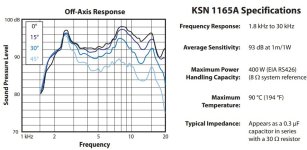
Impedance curve of classic Motorola KSN1041

From about 2k be little different than usual , 600 ohms to around 50 ohms

Drop in 8 ohm Zobel around 10 to 18uf to start curve around 2k
Bing...Straight line 8 ohms


Drop in 3rd order 5k crossover


Of course the FRD comes from old Motorola Datasheet
with gracious amounts of smoothing. But that is basic 5k super tweet
Impedance data is important if you add padding, the Zobel needs
fine tuning. All rather simple.
You just cant use conventional crossovers without Zobel
no transformer needed.

Many examples of being crossed too low.
With simple filters.
Like any driver, pound it out of bandwidth
bunch of distortion.
Use a steep filter, and impedance compensation
and cross around 4 , 5 , 6k
feasible to pair with maybe 3" or 4" mid/ wideband
Dirt cheap driver, crossover components would cost more.
And huge trendy 500 watt coils aren't needed.
Be helpful to have impedance measurement
to actually fine tune the crossover.
Dont need transformer, you can create whatever impedance
you want with resistor and cap, or basic passive Zobel
If you try to use conventional crossover without Zobel.
Be almost dead short.
With Zobel and resistor value can make it 6 , 8 , 10 ohms
whatever heck you want. Just important to have
impedance data to fine tune Zobel and crossover
Impedance curve of classic Motorola KSN1041
From about 2k be little different than usual , 600 ohms to around 50 ohms
Drop in 8 ohm Zobel around 10 to 18uf to start curve around 2k
Bing...Straight line 8 ohms
Drop in 3rd order 5k crossover
Of course the FRD comes from old Motorola Datasheet
with gracious amounts of smoothing. But that is basic 5k super tweet
Impedance data is important if you add padding, the Zobel needs
fine tuning. All rather simple.
You just cant use conventional crossovers without Zobel
no transformer needed.
Last edited:
Good idea to ensure there's some series resistance, for the reasons outlined in Planet10's post, unless you want to let out the magic smoke
Piezo, Brian Steele Blastoramas
https://www.diysubwoofers.org/projects/home/blastoramas/
https://techtalk.parts-express.com/...inence-beta-8a-with-the-grs-pz1016-2-x5-piezo
Updated with cheap Pyle neodymium compression driver, Brian Steele Blastoramas V2
https://www.diysubwoofers.org/projects/home/BlastV2/
Darren Kuzma The Golden Boys - Parts Express
https://projectgallery.parts-express.com/speaker-projects/the-golden-boys/
Last edited:
Yes, do that , but because the impedance @ 20kHz is now very low, you should add a 3.9 ohm resistor in seriesput 8 ohms in parallel to the piezo between plus and minus and 2.2 microfarad in line before it. this will help against 5khz resonance
with your positive input connection to protect both amp. & tweeter.
Last edited by a moderator:
Almost always when I see someone mention piezo tweeters, I think of the highly regarded Dahlquist DQ-10 of the 1970s. It was a 5-way(!) floorstander looking a lot like a Quad ESL-57 and using a Motorola(?) horn piezo. Here's a pair, w/excellent photos, someone bought in great condition.
Yeah exactly
Many examples of being crossed too low.
With simple filters.
Like any driver, pound it out of bandwidth
bunch of distortion.
Use a steep filter, and impedance compensation
and cross around 4 , 5 , 6k
feasible to pair with maybe 3" or 4" mid/ wideband
Dirt cheap driver, crossover components would cost more.
And huge trendy 500 watt coils aren't needed.
Be helpful to have impedance measurement
to actually fine tune the crossover.
Dont need transformer, you can create whatever impedance
you want with resistor and cap, or basic passive Zobel
If you try to use conventional crossover without Zobel.
Be almost dead short.
With Zobel and resistor value can make it 6 , 8 , 10 ohms
whatever heck you want. Just important to have
impedance data to fine tune Zobel and crossover
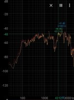
Impedance curve of classic Motorola KSN1041
View attachment 1224116
From about 2k be little different than usual , 600 ohms to around 50 ohms
View attachment 1224125
Drop in 8 ohm Zobel around 10 to 18uf to start curve around 2k
Bing...Straight line 8 ohms
View attachment 1224127View attachment 1224128
Drop in 3rd order 5k crossover
View attachment 1224133View attachment 1224134
Of course the FRD comes from old Motorola Datasheet
with gracious amounts of smoothing. But that is basic 5k super tweet
Impedance data is important if you add padding, the Zobel needs
fine tuning. All rather simple.
You just cant use conventional crossovers without Zobel
no transformer needed.
View attachment 1224135
Without smooting...some from internet.
Attachments
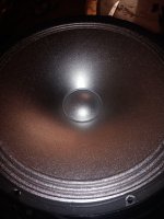
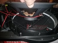
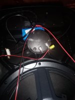
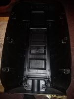
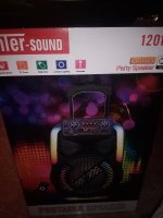
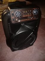
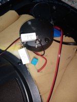
Portable bluetooth box with piezo which deserves attention.
Original is 2.2uF in line nothing else.
Will get some resistor from plus to minus and checking polarity.
Box got damping (had none) and the paper cone some aluminium treatment

Original is 2.2uF in line nothing else.
Will get some resistor from plus to minus and checking polarity.
Box got damping (had none) and the paper cone some aluminium treatment
Attachments
-
 IMG_20250221_172953.jpg564.1 KB · Views: 70
 -
 IMG_20250221_190614.jpg389.7 KB · Views: 76
 -
 IMG_20250221_174117.jpg395.2 KB · Views: 80
 -
 IMG_20250221_172037.jpg238.4 KB · Views: 72
 -
 IMG_20250221_172049.jpg173.3 KB · Views: 66
 -
 IMG_20250221_172115.jpg212.2 KB · Views: 69
 -
 IMG_20250221_171542.jpg322.4 KB · Views: 71
 -
 IMG_20250221_171527.jpg311.8 KB · Views: 71
this piezo tweeter sounds originally horrible came drastically obvious after cone and box treatment.
tweeter is wired with same polarity I am sceptic this is correct.
Measurement will show if there is a cancellation between both drivers
Measurement will show if there is a cancellation between both drivers
A TRUE Piezo Super Tweeter (piezo tweeter revisited)
- Thread starterAudio>X
- Start date2023-05-16 9:33 am
https://www.diyaudio.com/community/...tweeter-piezo-tweeter-revisited.399363/latest
put 8 ohms in parallel to the piezo between plus and minus and 2.2 microfarad in line before it.
Make that 22 ohm in parallel.
The RC circuit will attenuate the low frequency voltages thus reducing the risk of overloading the piezo and producing distortion.
A suitable crossover and high frequency attenuation arrangement for a small piezo, or parallel combination of small piezos, is shown in the attachment.
It comprises a 2.2 uF series crossover cap, then a 22 ohm shunt from hot to ground, then an optional series cap of about 0.15 uF for 6 dB attenuation.
Attachments

Back in the 1970's, when I subscribed to Australian HiFi magazine, I read a review & test of the Dahlquist DQ-10 that I remember >Almost always when I see someone mention piezo tweeters, I think of the highly regarded Dahlquist DQ-10 of the 1970s. It was a 5-way(!) floorstander looking a lot like a Quad ESL-57 and using a Motorola(?) horn piezo. Here's a pair, w/excellent photos, someone bought in great condition.
Because there are so many high frequency drivers spaced at quite a distance apart, the frequency response plot showed a lot of comb-filtering effect.
[ it was far from flat ]
In the subjective listening comments, they stated: Although these speakers represented a sound somewhat like an electrostatic speaker
there were some "strident high frequency notes present".
I can guarantee that those "strident notes" came from the Piezo's. I would love to see the full crossover network schematic diagram 🙂
PS. Great photo's !
update to post 29 in this thread.
The piezo tweeter must be reversed there is a suckout at 3khz. Will report when turning its phase if it gets more linear.
box 25cm measured between driver and tweeter

close to tweeter 5cm

The piezo tweeter must be reversed there is a suckout at 3khz. Will report when turning its phase if it gets more linear.
box 25cm measured between driver and tweeter
close to tweeter 5cm
piezo tweeter with reversed phase gets even worse - returned to before again. Also listening test showed same phase sounds better.
Highs sound now acceptable with 1 ohm in line, 1uF in line and 100 ohms across plus and minus of the tweeter. Makes a big difference.
Added some thin damping to the inner side of the metal basket. This is also a very audible reduction in colouration but doesn't do anything obvious to the frequency response.
added some more damping to the box

some EQ helps getting a more complete sound

Highs sound now acceptable with 1 ohm in line, 1uF in line and 100 ohms across plus and minus of the tweeter. Makes a big difference.
Added some thin damping to the inner side of the metal basket. This is also a very audible reduction in colouration but doesn't do anything obvious to the frequency response.
added some more damping to the box
some EQ helps getting a more complete sound
Attachments
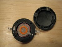
damping piezo tweeters with very fine damping material for free
covering the piezo paper cone with fine aluminium foil from the goldsmith
covering the piezo paper cone with fine aluminium foil from the goldsmith
piezo tweeters with thin aluminium foil from the goldsmith
special glue
special damping behind the cone
its from clothes which were dried in a machine


special glue
special damping behind the cone
its from clothes which were dried in a machine
I just thought that 'for the record', I should correct this post >Since they present a pure capacitance as an impedance, the resistor actually acts like a cap would for a dynamic (magnet - coil) speaker. A resistor forms a high-pass filter when in series. It's sorta counterintuitive.
Because the natural impedance of a Piezo tweeter is that of nearly pure capacitance, series resistance actually creates a low-pass filter.
The higher the series resistance, the more the 'top-end' roles off.
Adding series capacitance creates a broard-band level reduction. The lower the series capacitance > the more level reduction is increased.
For a series capacitor to act as a high-pass filter, resistance has to be added across the Piezo terminals.
The lower the resistance added across the terminals > the more the Piezo's impedance changes away from being capacitive AND the more
a series capacitor acts as a high-pass filter.
nice pictures of original Motorola tweeter ksn1025a
https://www.audioheritage.org/vbulletin/showthread.php?40987-The-piezo-fun-box/page2
just to learn what piezo construction was like in former times
https://www.audioheritage.org/vbulletin/showthread.php?40987-The-piezo-fun-box/page2
just to learn what piezo construction was like in former times
Attachments
- Home
- Loudspeakers
- Multi-Way
- Are Piezo Tweeters frowned upon?