Andrew,
Sorry, but I have the feeling that you missed the whole point.
Apart from the fact that your Head Amp design has an admirable low noise contribution thanks to a common base design, Nick’s comment against your claim was that it’s noise contribution is not constant as with a transimpedance amp with a zero input impedance.
The overall noise contribution of this desing is dependent on the Cart’s source resistance, caused by the attenuation of it’s 3.75R input resistance.
My posting was a pure mathematical exercise not to blame the amp but showing it’s dependency on Rsource.
Still giving excellent performance, but certainly not constant.
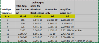
In the graph below you can see the amp’s noise contribution RTI against Rcart from 1 ohm to 50 ohm, showing this dependency even better.
In all cases a gain of 10 was used and the dotted line shows the trend line.
So, what you see is: SQRT((Overall noise RTI)^2-(Rcart's noise)^2).
With large values of Rcart, the amp's noise contribution is much lower as the noise generated by Rcart, but the lower Rcart becomes, the more both approach.
At Rcart = 3.75R, noise contribution is the same for both and 3dB additional noise will be added to the Cart's noise.
Hans

Sorry, but I have the feeling that you missed the whole point.
Apart from the fact that your Head Amp design has an admirable low noise contribution thanks to a common base design, Nick’s comment against your claim was that it’s noise contribution is not constant as with a transimpedance amp with a zero input impedance.
The overall noise contribution of this desing is dependent on the Cart’s source resistance, caused by the attenuation of it’s 3.75R input resistance.
My posting was a pure mathematical exercise not to blame the amp but showing it’s dependency on Rsource.
Still giving excellent performance, but certainly not constant.
In the graph below you can see the amp’s noise contribution RTI against Rcart from 1 ohm to 50 ohm, showing this dependency even better.
In all cases a gain of 10 was used and the dotted line shows the trend line.
So, what you see is: SQRT((Overall noise RTI)^2-(Rcart's noise)^2).
With large values of Rcart, the amp's noise contribution is much lower as the noise generated by Rcart, but the lower Rcart becomes, the more both approach.
At Rcart = 3.75R, noise contribution is the same for both and 3dB additional noise will be added to the Cart's noise.
Hans
Hans,
Here is my analysis. I adjusted the MC amp output load to give 5mV out (all ref 200uV input) - this is possible up until 12 Ohms after which the output gain adjust resistor must be set to open to get a little less than 5mV
The input noise is then calculated by subtracting the Rcart noise. So indeed the noise contribution is not flat but with the 12 Ohm Benz cart I still get <250 pV/rt Hz.
Nick's claim was not concerning the issue we are discussing here. He placed a 3.5 Ohm resistor from the input of the amp to ground (and not in series with the generator) and then fed that with a voltage generator with the associated cart resistance. That led to an input referred noise of 1.26V/rt Hz (see his post #52). When I repeated his analysis without the 3.5 Ohm to ground, I got the correct noise voltage. Anyway, as always, thank you for your input.
🙂
Attachments
Wayne, yes, you are right!If Nick thinks this is noisy he won't like my Burning Amp 2023 phono stage at all.
 Your "Pearl3" as an MC preamplifier is much worse than Russell's X-Altra (0.64 versus 0.22 nV/root Hz input shorted). In addition, in MM mode of "Pearl3", the 47 kOhm input resistor creates, according to Nyquist, a noise current of 0.59 pA/rootHz, which flows through a typical 500 mH 1 kOhm MM cartridge, and according to Ohm's law, creates a noise voltage of 1.89 nV/rootHz at a frequency of 1 kHz (and 13.1 @ 10 kHz !), which is 3 TIMES greater than 0.64. For reference, this is also noticeably worse than my "Cy-XXI" with a "passively cooled" 150 kOhm input and 1.08 nV/rootHz.
Why do you subtract Rcart noise? Is the noise of the cartridge removed by someone from the output signal? RTI include all noise sources at preamp output, divided by the preamp amplification @ 1 kHz. PS. And what is in your opinion the input node of preamp + cartridge, which must be identified as 0 dB signal point? It is not common emitters of ZTX951\851, but EMF of MC cartridge (before Rcart and Lcart), OK?The input noise is then calculated by subtracting the Rcart noise.
The MC cart is not being subtracted. It is added to the thermal noise equivalent resistance on 3.5 ohms. This is quite standard practice so I really don’t understand why you don’t get it. For any of the carts you use, we can calculate the total noise RMS style. What quickly becomes apparent is that with higher cart resistances, most of the noise is from the cart and not the amplifier.
The measured RTI spot noise at 1 kHz for the X-Altra MC input is 232pV/rt Hz. That includes PSU noise (50 pV/rt Hz). PSU noise and input noise will also add RMS style so it will be input thermal noise that dominates. That 232 pV/rt Hz noise is added RMS style to the cart noise to get the total RTI noise.
The measured RTI spot noise at 1 kHz for the X-Altra MC input is 232pV/rt Hz. That includes PSU noise (50 pV/rt Hz). PSU noise and input noise will also add RMS style so it will be input thermal noise that dominates. That 232 pV/rt Hz noise is added RMS style to the cart noise to get the total RTI noise.
Hi Andrew,
Why keep repeating that the superior X-Altra has a fixed RTI, while it is dependent on gain setting and Cart impedance, as shown in #101 for a 10x gain.
With higher gain RTI even improves a bit.
Nobody needing 20dB gain with a 40R Cart is looking for a head amp producing less then 500pV/rtHz. When needing 26dB gain the maximum Rsource a Cart can have is 24R and with an RTI of ca. 300pV/rtHz, you will still add an almost insignificant amount to the Cart’s noise.
Hans
Hello Hans
I’ve tried explaining that. Some people can’t see that the amplifier noise is a negligible part of total cart + amplifier noise for a typical MC cart. I spec’d it at 250 pV/rtHz given the measurements I did and published. You may say it’s a bit higher and I won’t argue that point.
In the other thread, the RTI noise was plotted with the output load set to 180 Ohms and cart resistance stepped from 3 to 18 ohms. The noise curves are there for all to see.
I’ve also explained to Nick in previous posts that no claim has been made that the total noise is fixed - it will go up the higher the cart resistance thermal noise.
I suspect there are other reasons that Nick has singled out the X-Altra MC/MM. Only he can answer that.
(When I spoke of input thermal noise dominating in post #105 above I was referring to input thermal noise dominating wrt PSU noise)
Last edited:
OK, if you want I answer.I suspect there are other reasons that Nick has singled out the X-Altra MC/MM. Only he can answer that.
Cy-XXI phono preamp advantages over X-Altra and Pearl3 are
1. Passive cooling ultra low capacitance input 150k/25pF : 5 dB Nyquist bonus to S/N ratio + no need of input LCR resonance adjustment for flat FR up to 38 kHz
2. Double differential stages scheme : high PSRR \ no add noises and ripples from simple PS as well as from drain current source noise
3. Output TransAdmittance stage with ActiPassive constant 40 dB loop gain RIAA EQ : ultralow THD with large overload margin, good RIAA accuracy, no THD increase @ LF, no problems with HF stability
4. No electrolytes: good sound and very compact size 20x45x3 mm suitable for freely installation @ tonearm basement of any turntable, - like Phaedrus Phlux / Clearaudio Absolute Phono but without the need to modify headshell\tonearm: no external interference/noise on the interconnect cable and no loss of signal quality
5. Newest JFE2140 input JFETs have Gfs/Ciss ratio 2.31 mS/pF as compared with LSK389`s 0.8 mS/pF and 2SK170`s 0.73 mS/pF. In Cy-XX phono preamp with 8 mA drain current JFE2140 has fourth root of (8/1.5)=1.52=3.64 dB less noise than LSK389 with 1.5 mA drain current as used in X-Altra MM input. That is to say two paralleled LSK389 have more noise than single JFE2140.
6. Real measured SNR 82 dB unweighted [
Attachments
Nick, you move the discussion from MC to MM and turning it into a game “I’m better than you”.
1) passive cooling brings a few dB’s extra that nobody really needs, just complicating things
2) better to put effort in a good supply.
3) all of these features can also be achieved with a VFA.
4) MM Carts are designed to include the cable capacitance. When mounting the amp in the TT it will become more difficult to tune to the correct capacitive load.
5) Nice, tomorrow we will have even more advanced dual Fet’s.
Only question that counts: does it produce better sound ?
6) For a top Phono amp, everything above 75dB-A doesn’t bring any improvement.
Hans

The idea is not to load MM cartridge with a rated load. With R 150 kOhm instead of 47 kOhm and C less than 100 pF, we get good linearity of the frequency response of up to 20 kHz and above. This is by electric voltage. But it is not known what will happen to the common frequency response, taking into account the mechanical properties of the cartridge.4) MM Carts are designed to include the cable capacitance. When mounting the amp in the TT it will become more difficult to tune to the correct capacitive load.
All phono cartridges have a scanning loss due to their stylus' finite (non-zero) dimension in the direction of travel of some very gentle slope, usually less than 2dB/Oct, and a two pole resonant response from the vinyl compliance x stylus (effective, referred to stylus) moving mass, within or slightly above hearing range.
MC cartridges give this response, and we've come to accept it as normal. For MM cartridges the choice between LCR loading optimized in the classic way, to flatten in-band response at the expense of a four pole ultimate rolloff, or some other loading, like SY's or Cordell's, that gives the raw mechanical response, seems to be somewhat a tone control setting choice.
All good fortune,
Chris
This is all true, but practical measurements of the frequency response at the load of MM cartridge with high resistance and low capacity give a fairly smooth frequency response. Of course, it is advisable to have statistics on a larger number of cartridges. If someone has the opportunity to make such measurements, it would be useful to publish results.
Read this posting and you will see that a generalisation with 150K is a shot in the dark.The idea is not to load MM cartridge with a rated load. With R 150 kOhm instead of 47 kOhm and C less than 100 pF, we get good linearity of the frequency response of up to 20 kHz and above. This is by electric voltage. But it is not known what will happen to the common frequency response, taking into account the mechanical properties of the cartridge.
https://www.diyaudio.com/community/attachments/mm-paper-pdf.1161286/
Hans
I don’t see anything terrible. With a load of 150K and 25pF, the AT150 model from this article gives +0.17 dB at 20 kHz. The full model with the tip gives +2.2 dB.
With a load of 47 kOhm, we have a greater dependence of the frequency response on the capacity of the cable, which the real user does not know. This is also a shot in the dark.
The high load resistance gives less the dependence of the frequency response on the cartridge L and impedance variations. The only drawback is that it is impossible to have a large input capacitance, the preamp should be near the tonearm.
Leoniv, I was enthusiastic about possibility of such alchemical transmutation of MM to MC cartridge. I tried, but the result was not what I expected. I got extended highs but subjectively recessed mids. Kind of "Loudness" effect.
Hans is guilty of dispelling my hopes. At list my Goldring 1012GX needs electrical resonance set in-band in order to get correct mids. It took me increasing of capacitive load from 100pF to over 300pF.
You can find details in this thread.
Hans is guilty of dispelling my hopes. At list my Goldring 1012GX needs electrical resonance set in-band in order to get correct mids. It took me increasing of capacitive load from 100pF to over 300pF.
You can find details in this thread.
Goldring 1012GX has 570 mg and 660 Ohms. The load 47K will give -3 dB at 13 kHz and -5.2 dB at 20 kHz. To fix this, use the capacity in the load. Recommended capacity from 150 to 200 pF.
150 pF gives -0.7 dB at 13 kHz and -4 dB at 20 kHz.
200 pF gives -0.3 dB at 13 kHz and -4.7 dB at 20 kHz.
Replacing the load by 150K and 25 pF gives +0.8 dB at 20 kHz and -3 dB at 53 kHz. But this is only for a simple electric model. In reality, the contribution will make a mechanical resonance and frequency losses, which in total may be insignificant. We need real measurements.
G1012GX has prominent mechanical resonance @20kHz. If you eliminate electrical resonance, you will get something similar to what I've described (recessed mids). Proper way to handle it is to set electrical resonance below 20kHz in order to flatten the peak @20kHz. Also, electrical Q should be chosen to rise upper-mids a little bit. You can find measurements in the previously linked thread. (I should update that thread with my latest measurements).
If I'm not mistaken, Nick use some kind of notch filter to flatten the mechanical resonance in his example.
If I'm not mistaken, Nick use some kind of notch filter to flatten the mechanical resonance in his example.
No, there is no notch filter. Nick considers only an electric frequency response without taking into account mechanical phenomena.
You make the big mistake by only looking at Lcart and Rcart.Goldring 1012GX has 570 mg and 660 Ohms. The load 47K will give -3 dB at 13 kHz and -5.2 dB at 20 kHz. To fix this, use the capacity in the load. Recommended capacity from 150 to 200 pF.
150 pF gives -0.7 dB at 13 kHz and -4 dB at 20 kHz.
200 pF gives -0.3 dB at 13 kHz and -4.7 dB at 20 kHz.
Replacing the load by 150K and 25 pF gives +0.8 dB at 20 kHz and -3 dB at 53 kHz. But this is only for a simple electric model. In reality, the contribution will make a mechanical resonance and frequency losses, which in total may be insignificant. We need real measurements.
Doing that, you miss about 90 percent of the real thing.
Read the PDF in my previous posting.
Hans
- Home
- Source & Line
- Analogue Source
- Pros and cons: prime MM\MC phonopreamps "X-Altra" & "LP797" vs "Cy-XXI"